Eureka AIR delivers breakthrough ideas for toughest innovation challenges, trusted by R&D personnel around the world.

Roof batten

a technology for roofs and roofs, applied in the field of roofs, can solve the problems of deterioration of roofs, permanent damage, interior mold, etc., and achieve the effects of reducing the number of roofs, facilitating production, and facilitating ventilation and drainag

Inactive Publication Date: 2005-01-06
BATTENS PLUS
View PDF20 Cites 45 Cited by
  • Summary
  • Abstract
  • Description
  • Claims
  • Application Information

AI Technical Summary

Benefits of technology

[0028] The battens of the present invention provide superior ventilation and drainage to eliminate the pooling of water on the roof surface, by virtue of the large chambers and the greater fluid exchange among spaces located between battens. When extruded and cut, the battens are easy to produce, low in price, lightweight, strong, and easily installed.

Problems solved by technology

While battens are useful in applying tiles to a roof, there are deficiencies in the traditional batten, foremost among them being the tendency of such battens to collect water on the roof surface underneath the tiles.
When water collects or stands in this manner, it will often infiltrate the paper or felt layer and into the underlying structure of the roof, leading to roof deterioration, interior mold, and permanent damage.
As traditionally assembled, battens create a dam behind the tiles, which can lead to storage of water on the underlayment.
This pooling can set up damage to a large portion of the felt underlayment.
Even double felting a tile roof will not protect it if large quantities of water are collecting on the roof surface, as it will eventually find its way into the underlayment.
Once water finds its way beneath the felt underlayment, the sheathing itself begins to fail, as water will make its way to any seam and then into the house.
This provides a complicated construction, with double layers of sheathing and battens required to assemble the roof.
The use of metal sheathing, however, adds to the weight and expense of this product over the traditional wooden batten.
However, with this design, the grooves can easily become clogged by accumulations of dirt and debris, minimizing the drainage achieved in practical application.
Batten designs that elevate the attachment layer over an open structure underneath, such as the double batted system, are complicated to produce and increase the cost of the roofing, in many cases requiring the use of special tiles for use with the roofing system.
Single layer battens with grooves, chambers or other openings provided for drainage and ventilation are susceptible to clogging from the dirt and debris that collects between battens on the roof surface.
Providing more frequent holes in the current designs would weaken the batten, by increasing the non-supporting regions of the batten.

Method used


Image

  • Roof batten
  • Roof batten
  • Roof batten

Examples


example 1

[0080] A roof batten is made by an extrusion process, using polypropylene heated and passed through a die to give the following dimensions. The batten is ½ inch high (12.7 mm), and 48 inches (1219 mm) long.

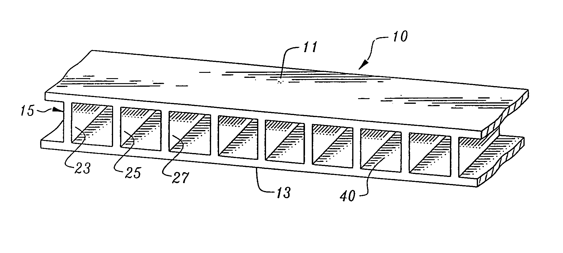
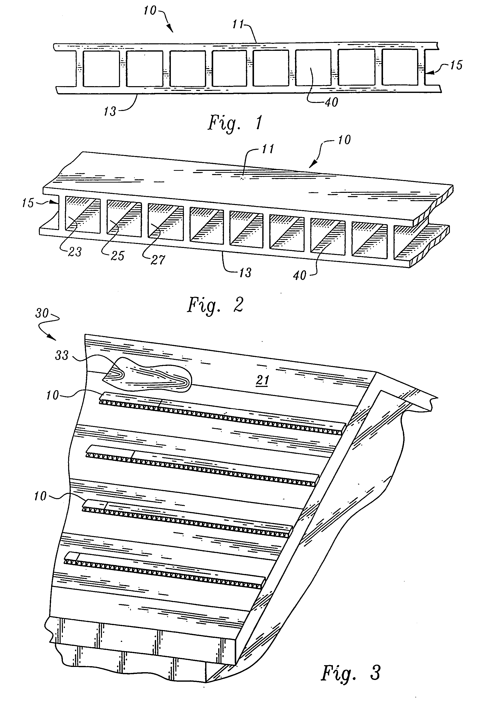
[0081] The plastic support structures of the battens are 0.044-inch-thick (1.12 mm)along the top and bottom surfaces, and 0.038-inch-thick (0.97 mm) in the region at the center of each of the vertical struts, gradually increasing in the outer regions of the struts closer to the interface with the surfaces, to about 0.062 inch thick (1.57 mm). The struts and upper and lower surfaces form chambered openings measuring 0.372 inch wide by 0.412 inch high (0.94 by 1.05 cm). One-hundred and fourteen chambers are formed in the batten.

[0082] Viewed from the front, each chamber of the batten has a square area of approximately 0.987 cm. From the same front view, the square area occupied by the plastic structural elements, surfaces and struts, corresponding to each chamber, is only about 0....


PUM


Abstract

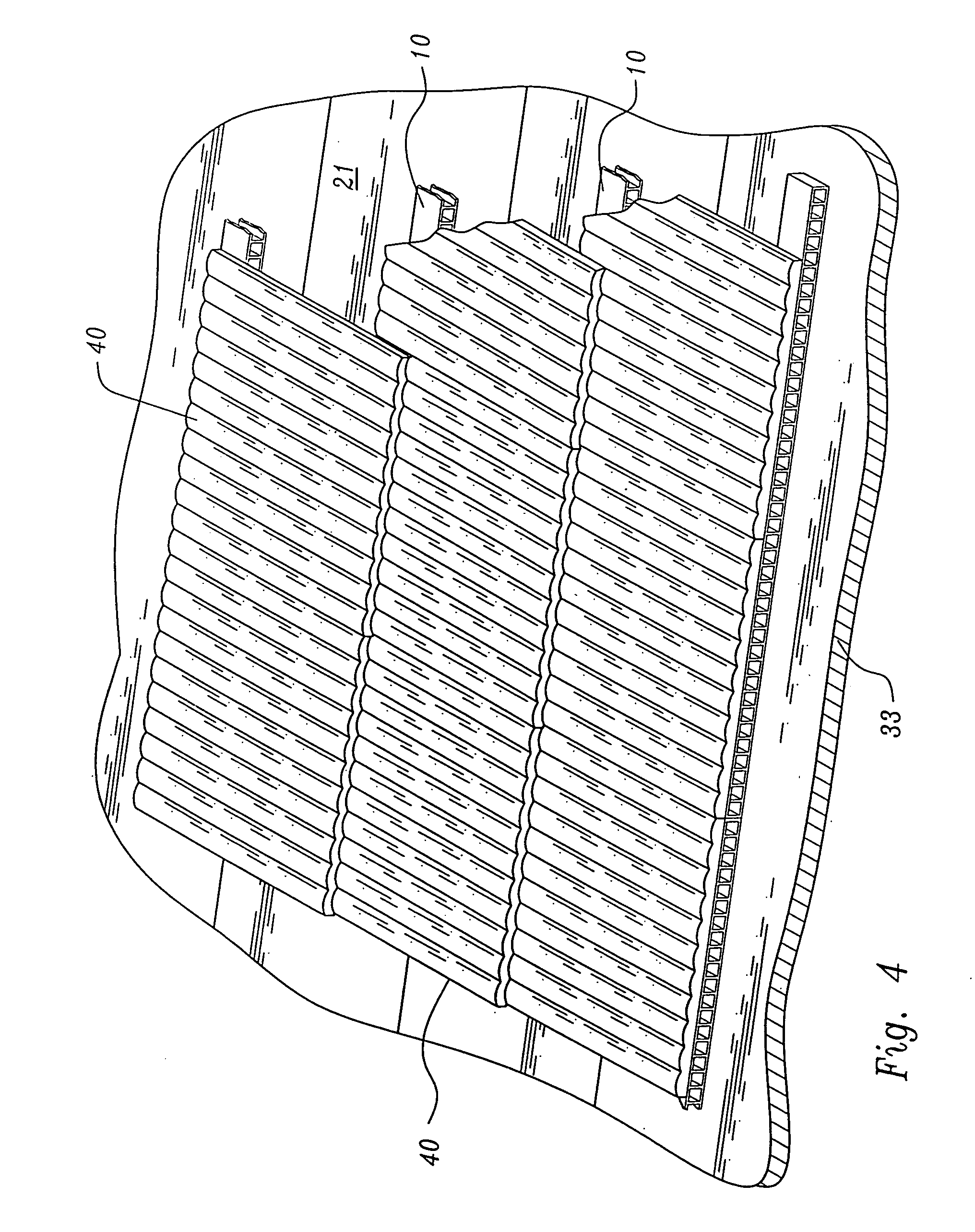
A roof batten integrally-formed of plastic with spaced, generally parallel upper and lower surfaces and a series of struts connecting the upper and lower surfaces, to form chambers permitting the fluid passage from the back edge to the front edge of the batten when it is affixed generally horizontally along a roof surface.

Description

BACKGROUND OF THE INVENTION [0001] 1. Field of the Invention [0002] This invention relates to roof battens used for applying tiles to a roof, and, more particularly, to a batten product integrally-formed of plastic. [0003] 2. Description of Related Art [0004] Tile roofs typically include several layers of materials. Over the trusses and / or rafters there is often a layer of exterior plywood or other sheathing, covered with roofing paper or felt which is conventionally applied, the tile underlayment. Roof battens are applied directly to this underlayment, with the tiles overlaying the battens. [0005] Roof battens are conventionally produced as 1 inch by 2 inch wooden elements. Battens are typically secured to a sloping roof in generally horizontal lines, such as through nailing, screwing or stapling, at intervals dictated by the tiles to be applied over the battens. An element on the tiles is supported along the elevated back edge of the batten. [0006] While battens are useful in appl...

Claims


Application Information

Patent Timeline
IPC IPC(8): E04D12/00E04F17/00
CPCE04F17/00E04D12/004E04F19/061
Inventor ANDERSON, TED F.
Owner BATTENS PLUS
Why Eureka
Eureka Blog
Learn More