
Optical reader comprising illumination assembly and solid state image sensor

an optical reader and illumination assembly technology, applied in the field of hand-held optical reading devices, can solve the problems of affecting the reading process, etc., and unable to be dealt with in this way for a long tim

Inactive Publication Date: 2004-12-30
HAND HELD PRODS
View PDF99 Cites 44 Cited by
  • Summary
  • Abstract
  • Description
  • Claims
  • Application Information

AI Technical Summary

Benefits of technology

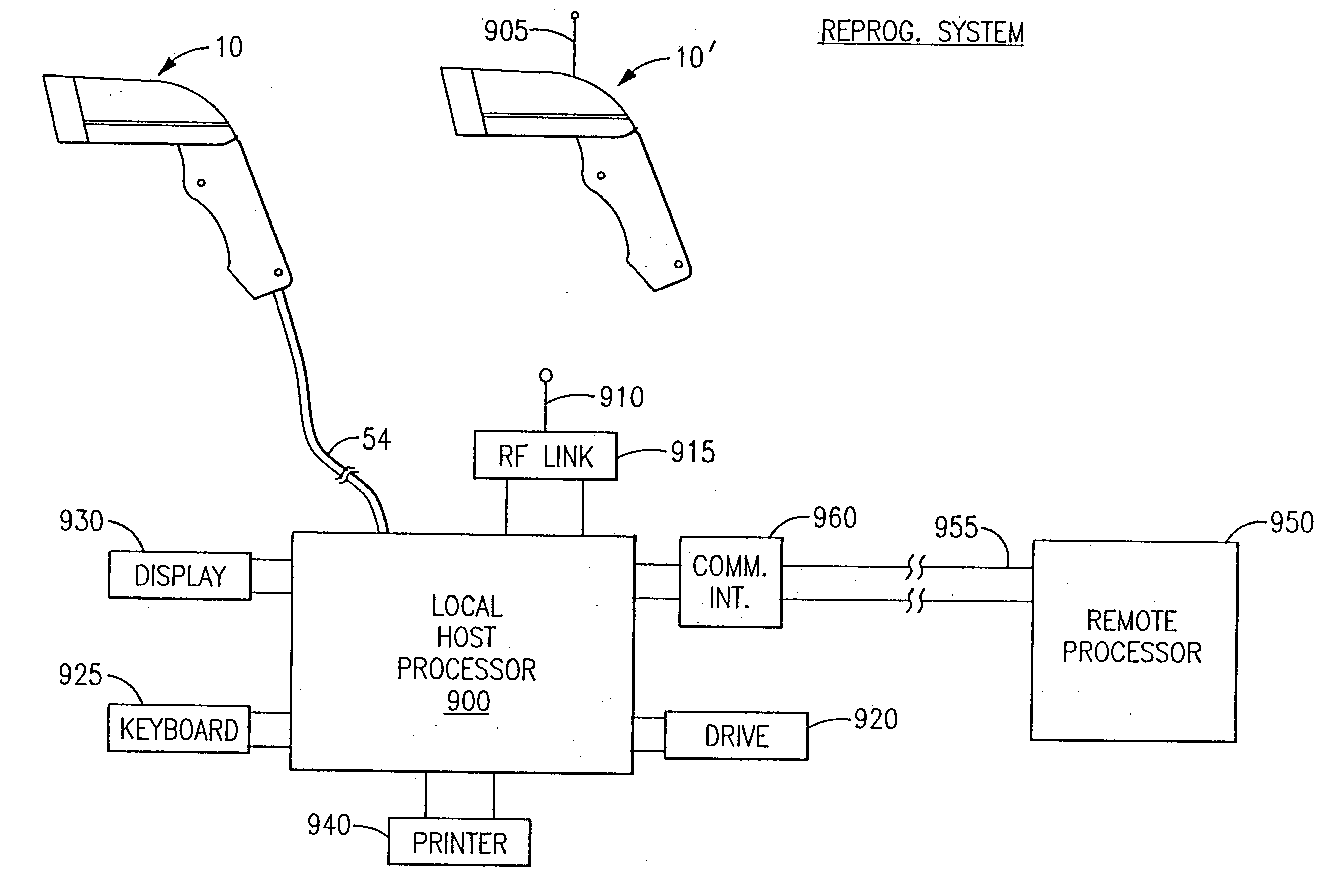
The present invention is an optical scanning and decoding apparatus and method that combines improved scanning-decoding and autodiscrimination features in a way that allows users to easily change the operating mode of the reader for optimal performance under current conditions. The apparatus and method also enable users to reprogram the reader from an external source, either on-site or off-site, and to edit the parameter table of the reader. Additionally, the invention provides for improved autodiscrimination features, such as one-shot and tracking relationships, to speed up and improve the decoding process. Overall, the invention improves the efficiency and flexibility of optical reading apparatuses and methods.

Problems solved by technology

Readers of the above-described type have the disadvantage that, if they are operated under relatively heavy decoding loads, i.e., are required to rapidly scan symbols that have a relatively high data content, the tracking relationship or synchronism between the scanning and decoding phases of the reading process will break down.
This is because under heavy decoding loads the decoding phase of a read operation takes longer than the scanning phase thereof, causing the decoding operation to lag behind the scanning operation.
While this time lag can be dealt with for brief periods by storing the results of successive scans in a scan memory and decoding the results of those scans in the order of their occurrence when the decoder becomes available, it cannot be dealt with in this way for long.
This is because, however large the scan memory, it will eventually overflow and result in a loss of scan data.
This is in spite of the fact that the 1D / 2D autodiscrimination is known to involve heavy decoding loads of the type that give rise to tracking problems.
As new and / or improved 1D and 2D bar code symbologies, and as additional 1D and 2D decoding programs come into widespread use, previously built optical readers may or may not be able to operate therewith.
To the extent that they cannot operate therewith, such previously built optical readers will become increasingly obsolete and unusable.
Because of the expense of the former and the time delays of the latter, neither of these approaches may be practical or economical.
The above-described problem is compounded by the fact that, if an optical reader is not equipped to operate as a tracking reader, it may not be possible to reprogram it to use an autodiscrimination program that is designed to be executed in conjunction with tracking.
Alternatively, the scan rate may be decreased, although this reduction will adversely affect performance when low data content symbols are read.

Method used


Image

  • Optical reader comprising illumination assembly and solid state image sensor
  • Optical reader comprising illumination assembly and solid state image sensor
  • Optical reader comprising illumination assembly and solid state image sensor

Examples


first embodiment

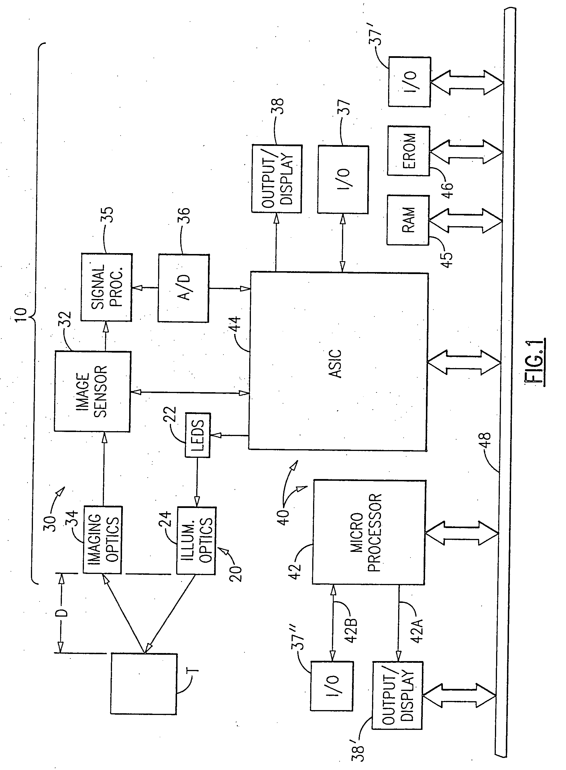
[0240] In the invention, both the scanning and decoding phases of the reading process proceed without interruption. In embodiments of this type a relatively large number of blocks of scan data are stored in and / or shifted through a relatively large memory space. As this occurs, address information (e.g. address pointers) which is indicative of the beginnings and endings of the scan blocks are updated, substantially in real time, so that the reader can at all times keep "track" of which block of scan data is the most recently completed block. Then, as each decoding cycle is completed, it is immediately followed by another decoding cycle which begins at the beginning of the most recently completed block of scan data, skipping over any then older blocks of scan data. In this way, both the scanning and decoding operations take place at a substantially 100% utilization rate, thereby assuring a high data throughput rate.

second embodiment

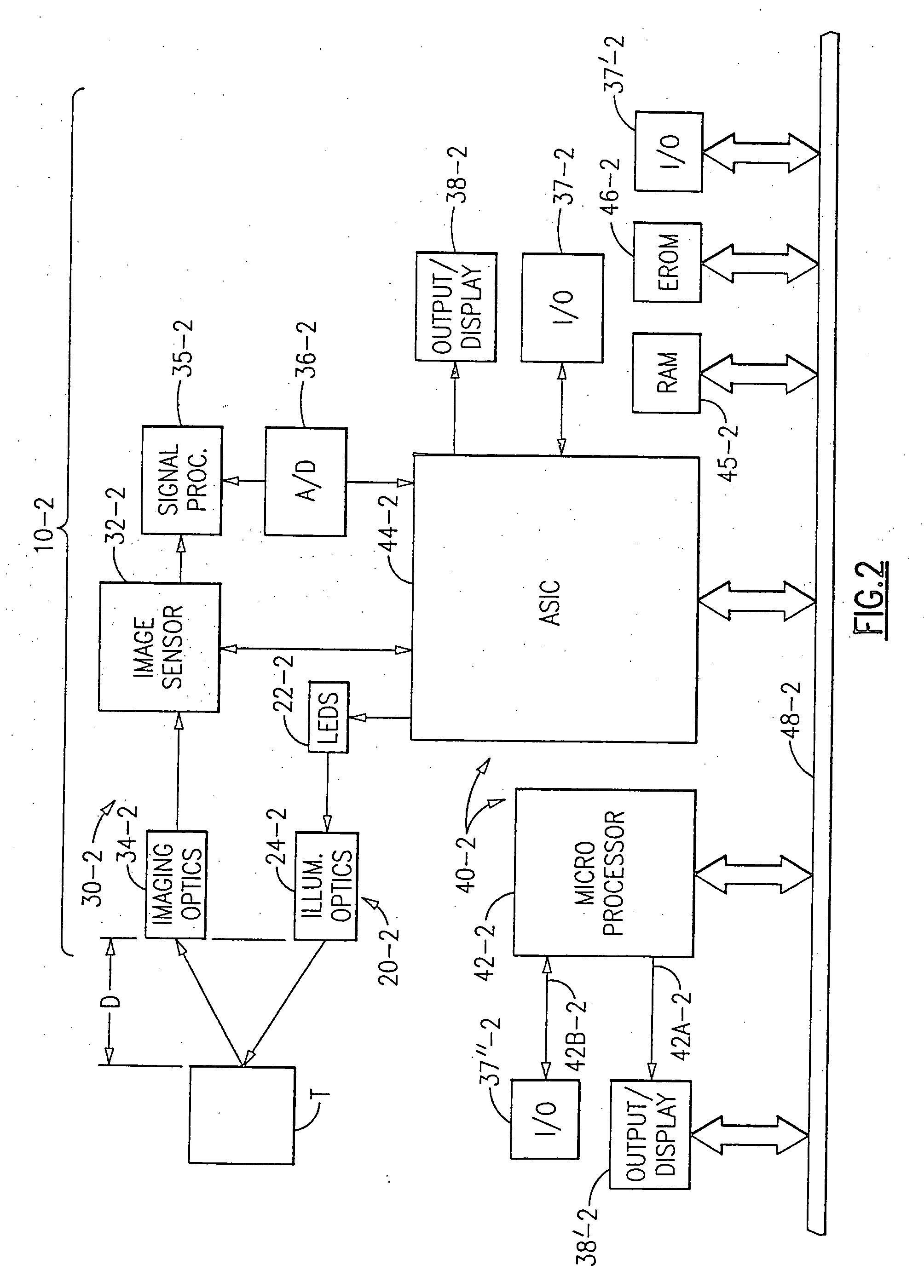
[0241] In the invention, the scanning and decoding phases of the reading process preferably (but not necessarily) proceed without interruption. In embodiments of this type blocks of scan data are stored in two or more sequentially selected memory spaces, having a predetermined size, scan data for each newly begun scan being written over the scan data in the memory space with the then oldest complete block of scan data. As this occurs, the memory space with the then most current block of scan data may be identified using an address pointer which directs the reader to one of the known scan data starting addresses.

[0242] Either of the two above-described embodiments of the invention may be practiced using either a 1D image sensor or a 2D image sensor, such as an image sensor of the charge coupled or CCD type. In the case of bar code symbols, this is true whether the bar code symbols are 1D symbols or 2D symbols. This does not, however, mean that embodiments which use 1D image sensors h...


PUM


Abstract

An optical reader for reading decodable indicia is provided. In one embodiment, the optical reader can include an image sensor. In one aspect, the optical reader can be configured to read bar codes such as 1D bar codes. Particular methods and apparatus for reading decodable indicia are described.

Description

[0001] CROSS REFERENCES TO RELATED APPLICATIONS[0002] This application is a continuation of copending U.S. patent application Ser. No. 10 / 227,889 filed Aug. 26, 2002, which is a continuation of U.S. patent application Ser. No. 09 / 651,162 filed Aug. 30, 2000, which issued as U.S. Pat. No. 6,491,223, which is a continuation of U.S. patent application Ser. No. 09 / 385,597 filed on Aug. 30, 1999, which is a continuation-in-part of U.S. patent application Ser. No. 08 / 839,020 filed Apr. 23, 1997, which issued as U.S. Pat. No. 5,965,863 on Oct. 12, 1999, which is a continuation-in-part of U.S. patent application Ser. No. 08 / 697,913 filed on Sep. 3, 1996, which issued as U.S. Pat. No. 5,900,613 on May 4, 1999, which is a continuation-in-part of U.S. patent application Ser. No. 08 / 516,185 filed Aug. 18, 1995, which is now abandoned, which is a continuation-in-part of U.S. patent application Ser. No. 08 / 205,539 filed on Mar. 4, 1994, which issued as U.S. Pat. No. 5,463,214, the aforementioned ...

Claims


Application Information

Patent Timeline
Patent Type & Authority Applications(United States)
IPC IPC(8): G06K7/10G06K7/14G06K17/00G06K19/06
CPCG06K7/10544G06K7/10851G06K7/14G06K7/1491G06K17/0022G06K19/06037G06K2207/1017G06K7/10821
Inventor LONGACRE, ANDREW JR.EHRHART, MICHAEL A.KOZIOL, THOMAS J.HUSSEY, ROBERT M.PARKER, JAMES A.
Owner HAND HELD PRODS
Learn More