Automated self-propelling endoscope

a self-propelling endoscope and automatic technology, applied in the field of self-propelling endoscopes, can solve the problems of long time that is required to examine the full length of the colon, the walls of the colon often fail to direct and guide the scope, and the obstruction of colonoscopy

Inactive Publication Date: 2004-12-23
BERNSTEIN LIONEL M
View PDF22 Cites 42 Cited by
  • Summary
  • Abstract
  • Description
  • Claims
  • Application Information

AI Technical Summary

Benefits of technology

[0018] Another object of the present invention is to provide a highly effective self-propelling endoscope with minimal alteration to the scope design.

Problems solved by technology

However, a major impediment to colonoscopy is the long time that often is required to examine the full length of the colon.
Further, the tubular colon is tortuous and highly flexible, and its walls often fail to direct and guide the scope as it is moved into the colon.
With only manual insertion efforts, progression of the distal end of the scope into the colon is successful for the first few short distances; but as the length of penetration increases and tortuous configurations of bowel need to be negotiated, the difficulties increase greatly, even with visual directional guidance of the tip of the scope.
Many examinations require much time, and many are terminated before the examination is complete.
Colonoscopic examinations are costly, and part of this is due to the amount of professional time required for the complete examination.
An analogous problem exists for the small bowel endoscope (enteroscope).
As a result, this is a rarely used procedure.
1. Major efforts have been expended and are under way to devise innovative methods for transporting the endoscope to where it needs to be with appropriate control, timeliness, safety, ease and comfort; this confirms the importance of these continuing needs.
2. The proximal-push mechanism is central and necessary for propelling a colonoscope, but it is not fully sufficient. Many investigators have deliberately attempted to augment the proximal-push with other forces to propel the colonoscope to meet the described needs.
3. it is becoming progressively more difficult to clearly identify the boundaries between technical support of medical / surgical clinical gastroenterology and the robotics supporting minimally invasive surgery (MIS).
4. In the attempts to innovate more effective endoscopic instruments, some investigators have developed instruments that come to look less and less like current endoscopes. Many have substituted new complicated technologies that are not superior to current colonoscopes to supplant existing scopes rather than creating new systems that can utilize the very mature, superb existing scopes. Many proposals rely on moving parts gaining traction against the bowel wall, or pushing on the wall, or that use pneumatic suction to adhere to the wall, all of which may alter or injure the mucosa. Others significantly increase the bulk of instruments that are inserted into the colon.
To use this effect in a real-life endoscopy context, a major challenge involves devising a system in which such a "distal pull" can be effected when the scope is not in a linear configuration, but rather follows multiple curves outside the body and as it moves through the bowel.

Method used


Image

  • Automated self-propelling endoscope
  • Automated self-propelling endoscope
  • Automated self-propelling endoscope

Examples


Embodiment Construction

and Functions of Rack One and Rack Two for Propelling the Eendoscope Forward

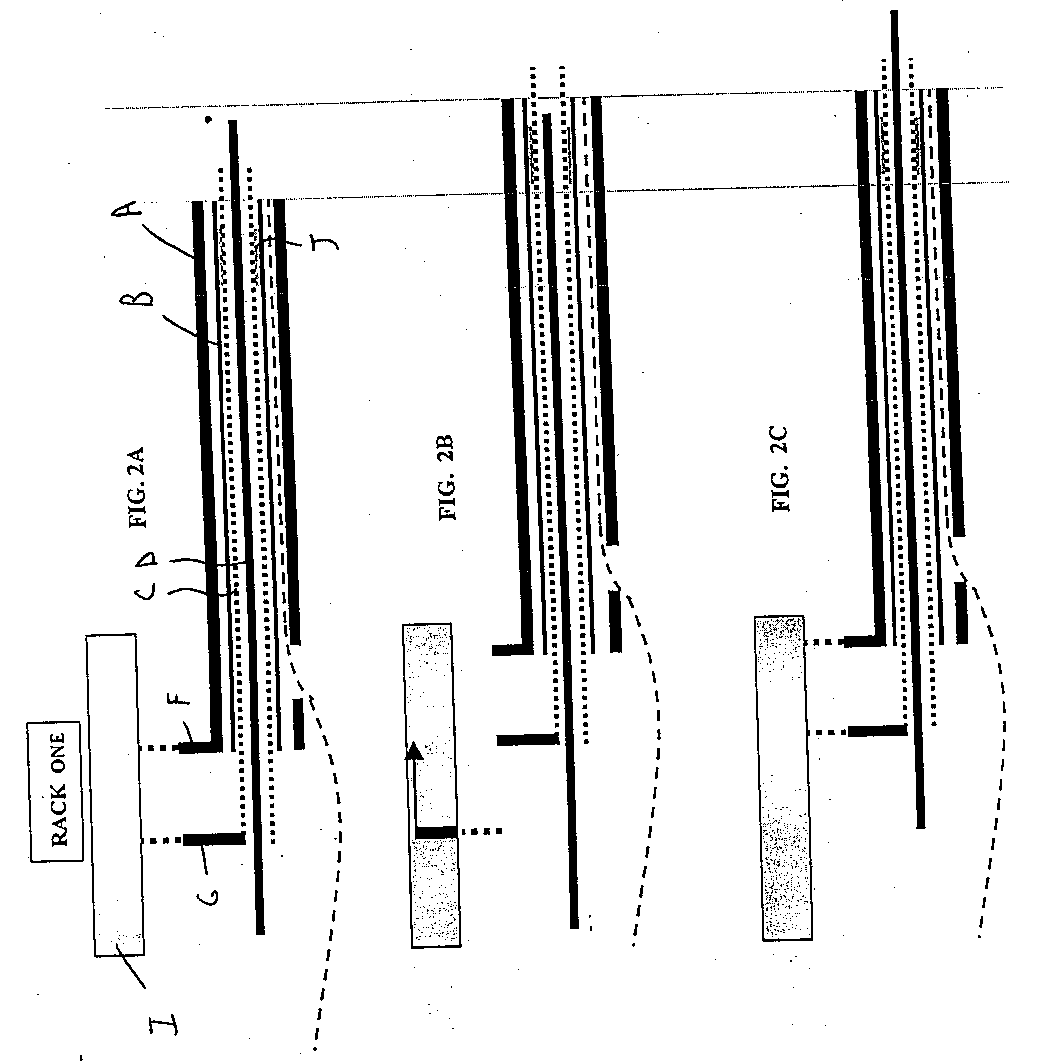
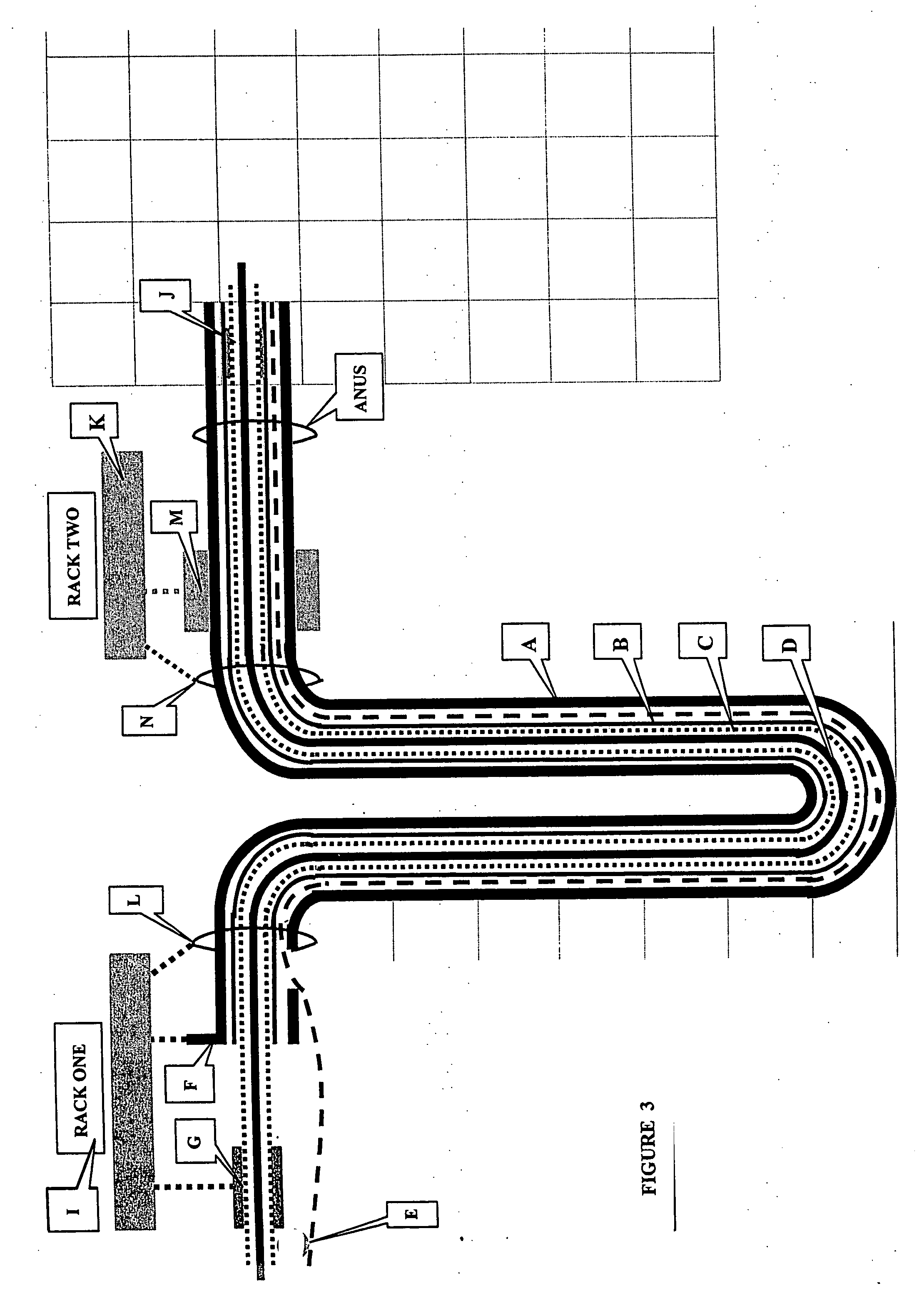
[0054] FIG. 3 depicts Rack One and Rack Two at the beginning of a propelling cycle. Rack One sits upon and is strongly fastened to a platform or table located adjacent to the proximal end of the endoscope. It has two potential coupling mechanisms, each designated by a dotted line when active. In FIG. 3, the vertical line attached to the coupling of the proximal end of the obturator channel F establishes a fixed and stable location for it; the proximal end of the obturator channel does not change its location during the entire operation of the automated propelling operation. This stability is enhanced by a similar firm coupling to rigid ring L through which the scope passes. Beyond the ring L is the loop that consists of the major length of the endoscope. The coupling mechanism at point G, including a pair of clamps, holds the EXT-obturator stationary with respect to Rack One I.

[0055] Electrical motors of Rac...


PUM


Abstract

An improved mechanism for an automated self-propelling endoscope. The system augments the conventional "proximal-push" mechanism commonly used in colonoscopy with an innovative "distal-pull" mechanism. The distal-pull mechanism includes external application of a force at the proximal end of the endoscope that is translated into force that is exerted upon and moves the distal (leading) end of the scope further into the colon.

Description

[0001] This application claims priority from U.S. Provisional Patent Application Ser. Nos. 60 / 286,366, entitled "Mechanism For Automated Self-Propelling Endoscope," filed Apr. 26, 2001, and 60 / 290,658, entitled "Improved Mechanism For Automated Self-Propelling Endoscope," filed May 15, 2001. The disclosures of these provisional patent applications are incorporated herein by reference in their entireties.[0002] 1. Technical Field[0003] The present invention relates to an improved mechanism for an automated self-propelling endoscope.[0004] 2. Discussion of the Related Art[0005] The flexible fiberoptic colonoscope has provided direct visualization of the inner surface of the entire colon, and has greatly influenced the diagnosis and treatment of colonic diseases over the past three decades. It is pervasively used throughout the U.S. and much of the industrialized world. It provides information that is complementary to common radiologic, CT scan, MRI, and other sophisticated imaging sca...

Claims


Application Information

Patent Timeline
IPC IPC(8): A61B1/005A61B1/31
CPCA61B1/0053A61B1/31
Inventor BERNSTEIN, LIONEL M
Owner BERNSTEIN LIONEL M
Why Eureka
Try Eureka