
Cargo roller system for cargo handling

a cargo and roller technology, applied in the direction of transportation items, loading/unloading vehicle arrangment, refuse collection, etc., can solve the problems of other pallets (transport trucks, generally larger and more rugged)

Inactive Publication Date: 2004-12-09
ENGINEERED SUPPORT SYST INC
View PDF34 Cites 93 Cited by
  • Summary
  • Abstract
  • Description
  • Claims
  • Application Information

AI Technical Summary

Problems solved by technology

The variation in weight, shape, size, and other characteristics of the materials needed to be transported leads to numerous logistical problems in getting materials from the point of manufacture to the soldier in the field.
Often, materials need to be transported by aircraft to reach a distant theater, but usually transport aircraft cannot land at the forward edge of the battle area or other similar points where the materials are most needed.
Other pallets (referred herein as "platforms") used by transport trucks, on the other hand, are generally larger and more rugged because trucks are not as dependent on weight limits as aircraft.
This series of steps is inefficient, requires significant man-hours of labor, and is a hindrance to getting materials to the supply point as quickly as possible.
While it may at first appear that a 463L pallet could be loaded directly onto a platform, such a process has a significant problem because 463L pallets have flat bottoms and typical platforms have generally flat tops.
Therefore, such a loading and unloading procedure results in high friction between the 463L pallet and the platform.
This in turn results in slow and awkward handling and damage to both platform and pallet during loading and unloading.

Method used


Image

  • Cargo roller system for cargo handling
  • Cargo roller system for cargo handling
  • Cargo roller system for cargo handling

Examples


Embodiment Construction

)

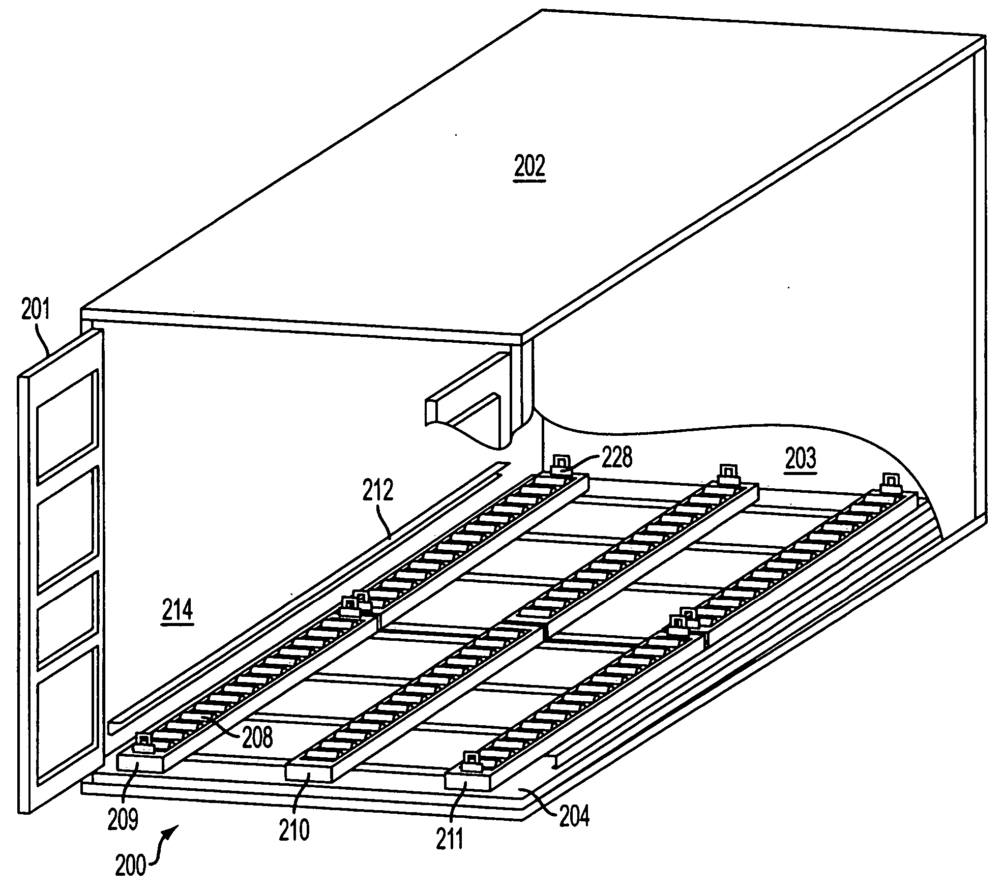
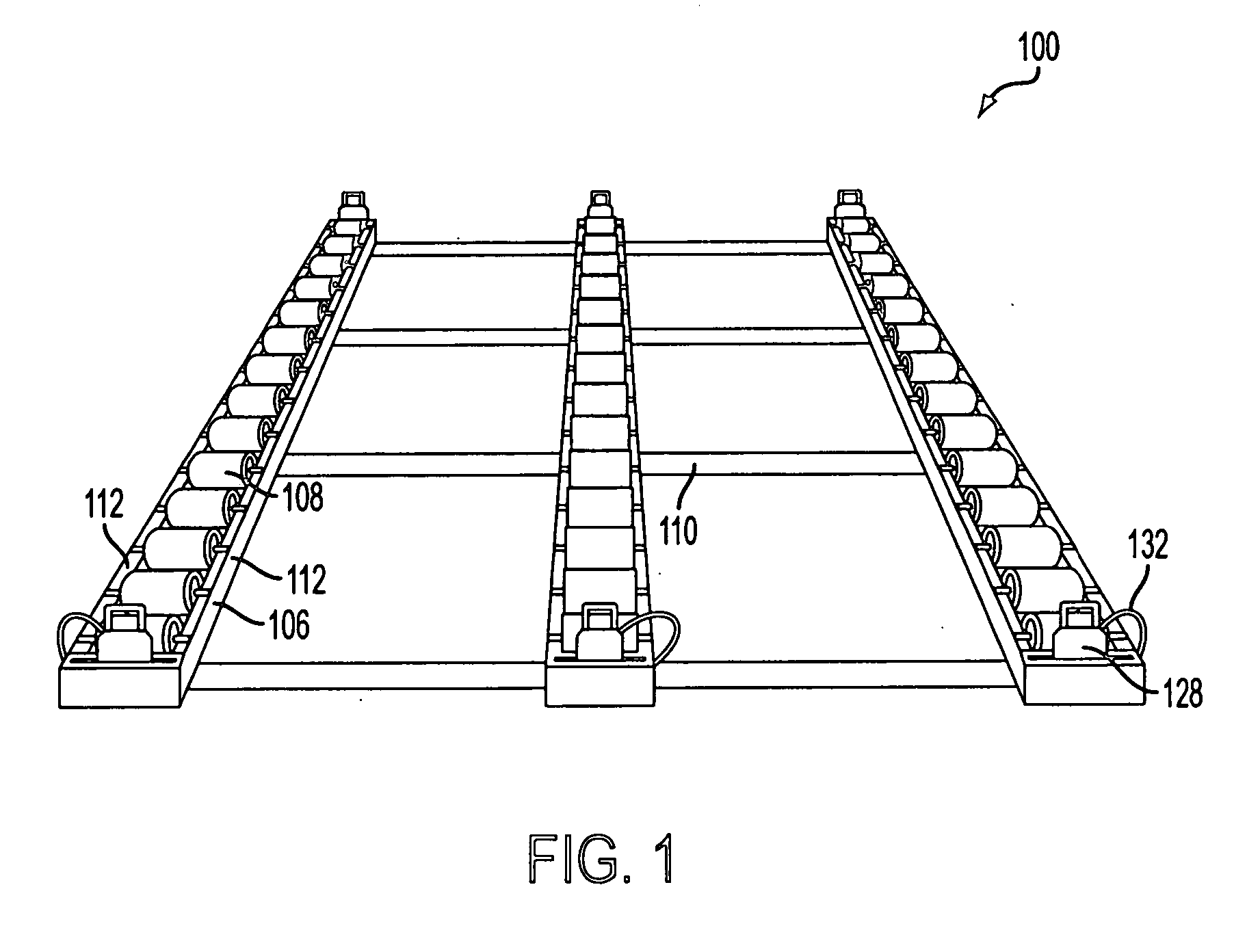
[0021] FIG. 1 depicts an embodiment of a roller unit (100) of the present invention that will be used to describe several portions of the roller unit (100) that also may be found in other embodiments. The roller unit (100) generally comprises at least one roller tray (106) in which is mounted at least one roller (108). The number of rollers (108) per tray and the number of trays (106) of rollers in any embodiment will depend upon the specific use to be made of the roller unit (100) and is a matter of engineering design. In the embodiment of FIG. 1 there are three trays (106), each tray comprising fourteen rollers (108). Here, the trays (106) are rigidly attached to one another by slats (110) that are welded between the trays (106). Generally, where a roller unit (100) is comprised of more than one tray (106), the trays (106) may be held together by any practical device, including a crosspiece of any type, such as a slat or a pipe having any practical cross section, or a plate-type,...


PUM


Abstract

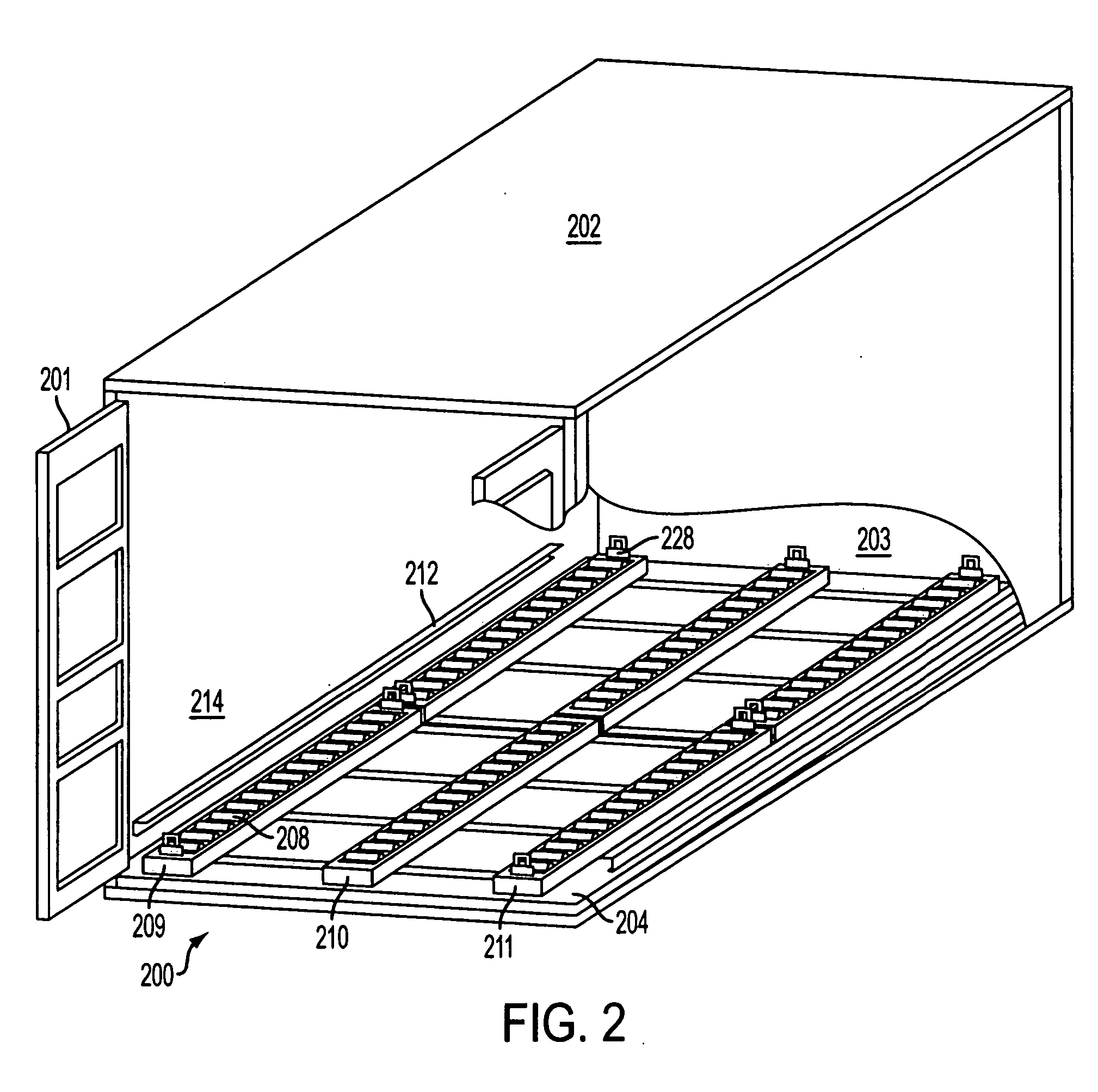
A roller unit that can be used to retrofit a cargo carrying surface makes loading and unloading of the cargo carrying surface easier by transforming the cargo carrying surface to include a conveyor system. The roller unit includes at least two trays in which are mounted rollers, the trays being connected by a crosspiece. The roller unit is designed to be installed on cargo carrying surfaces such as portable platforms, including Flatracks or CROPs, and in cargo containers of any type.

Description

[0001] This application claims the benefit of U.S. Provisional Application No. 60 / 460,960, filed Apr. 7, 2003, and is a Continuation-in-Part of U.S. Utility patent application Ser. No. 10 / 462,382, filed on Jun. 16, 2003, which claims the benefit of U.S. Provisional Application No. 60 / 389,272, filed Jun. 15, 2002, the entire disclosures of which are herein incorporated by reference.[0002] Not Applicable.[0003] 1. Field of Invention[0004] The invention generally provides systems and methods for loading cargo into containers and onto platforms using rollers. More particularly, the invention provides a framework having rollers which framework may be placed in cargo containers or on platforms to retrofit such equipment with roller systems for aiding in the loading of such equipment.[0005] 2. Description of Related Art[0006] Militaries around the world use a wide variety of different transport vehicles for getting materials that are needed for effective combat operations from the plants o...

Claims


Application Information

Patent Timeline
IPC IPC(8): B65D88/12B65D88/14B65D88/54B65D90/00
CPCB65D88/129B65D88/14B65D88/542B65D88/546B65D90/0033
Inventor NEUMANN, KENNETH M.KOZICH, ANOTHONY L.
Owner ENGINEERED SUPPORT SYST INC
Learn More