Combination of devices operational to increase the efficiency of storage tank or flow-through type waterheaters and hydronic boilers

Inactive Publication Date: 2004-11-25
VELKE WILLIAM H
View PDF10 Cites 3 Cited by
  • Summary
  • Abstract
  • Description
  • Claims
  • Application Information

AI Technical Summary

Benefits of technology

[0013] It is an object of the present invention to provide an effective method and a combination of devices operational in accordance with such method, to significantly improve the performance and efficiency of combustion equipment like storage tank or flow through type water heaters and hydronic boilers. Such method is based on providing a novel combination of pre-treatment procedures consisting of:
[0014] 1) altering the condition of fuel prior to ignition in order to improve combustion efficiency,
[0015] 2) altering the condition of combustion air prior to it being mixed with said fuel in order to improve its oxygen ratio,

Problems solved by technology

Said water conduit is of a very limited surface configuration for the purpose of providing efficient heat transfer from the combustion and flue pass area to the water, and a significant amount of energy is thereby unused and wastefully exhausted.
This disclosure is not suitable to function as a water storage heater, because the size of its annular combustion area in the center of the casing, and the configuration of pipes employed as water conduit area, limit the water storage volume and heat transfer water surface area.
The usual burner configuration presently employed in combustion chamber areas, as well as the fuel supply manifolds leading to such burner configuration, do not provide adequate opportunity for the necessary pre-conditioning of a fluid hydrocarbon fuel prior to its ignition.
However, it has now been found that the pre-heating of combustion air is more detrimental to the combustion process than any relative benefit derived from the increased energy input.

Method used


Image

  • Combination of devices operational to increase the efficiency of storage tank or flow-through type waterheaters and hydronic boilers
  • Combination of devices operational to increase the efficiency of storage tank or flow-through type waterheaters and hydronic boilers
  • Combination of devices operational to increase the efficiency of storage tank or flow-through type waterheaters and hydronic boilers

Examples


Embodiment Construction

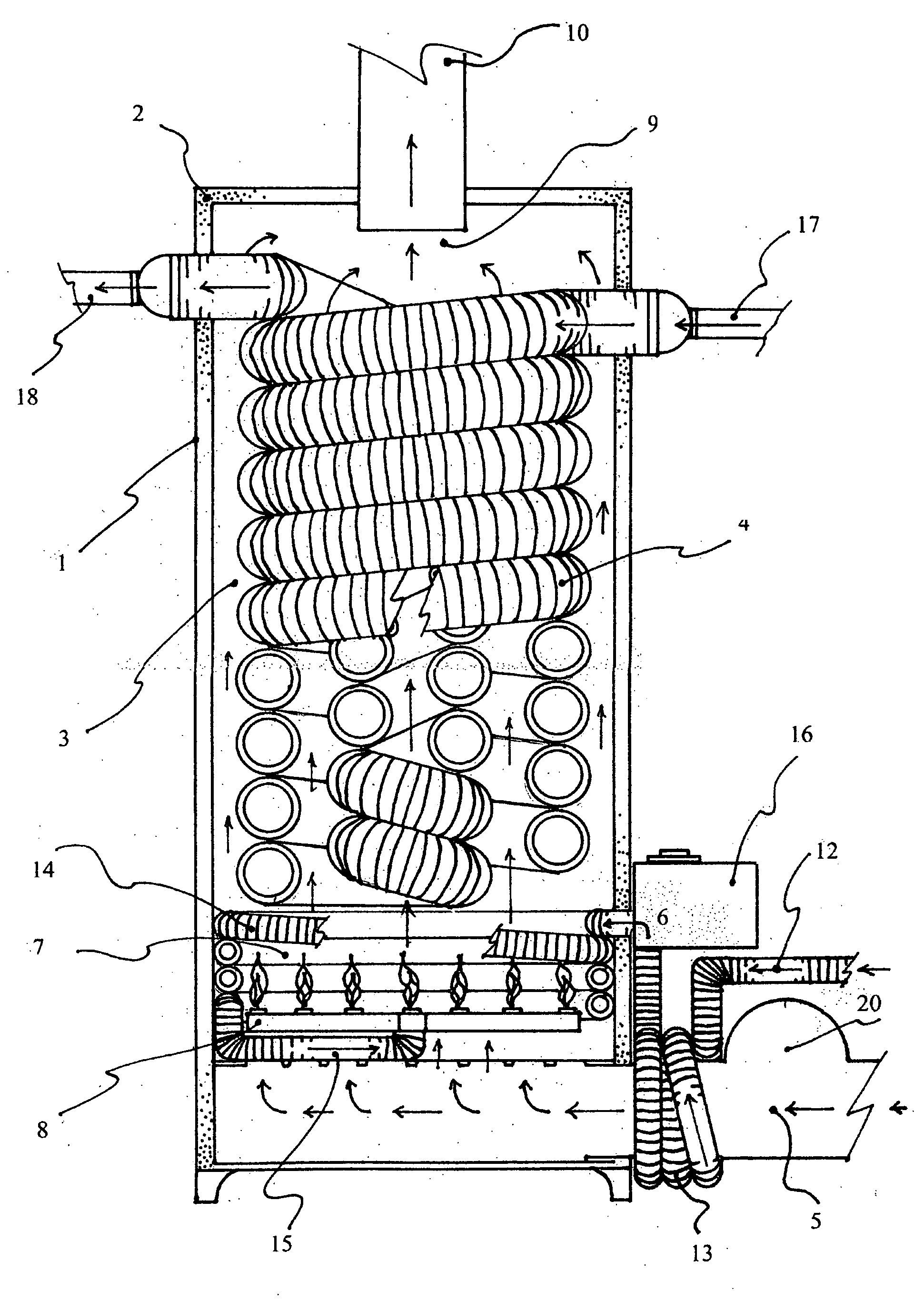
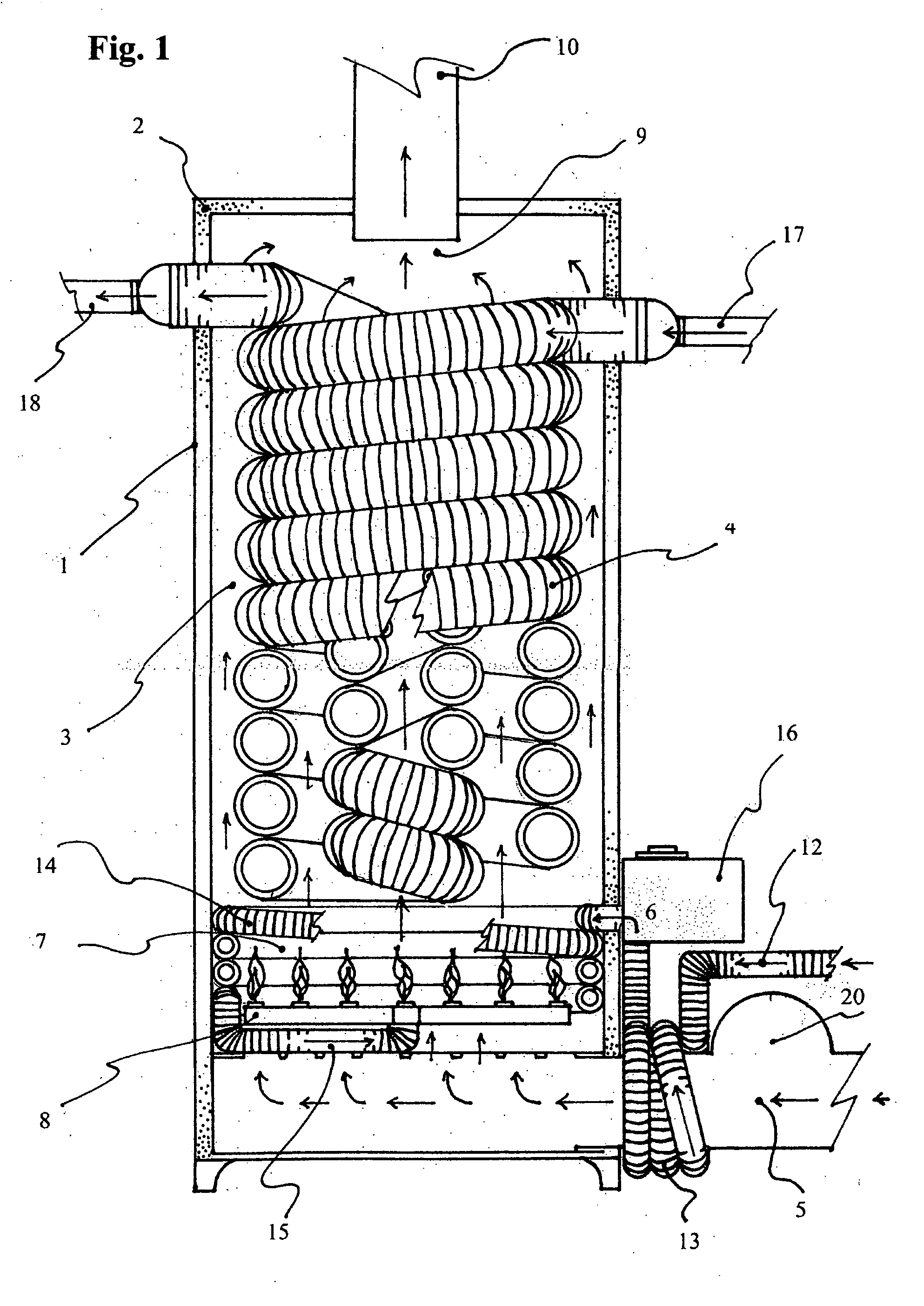
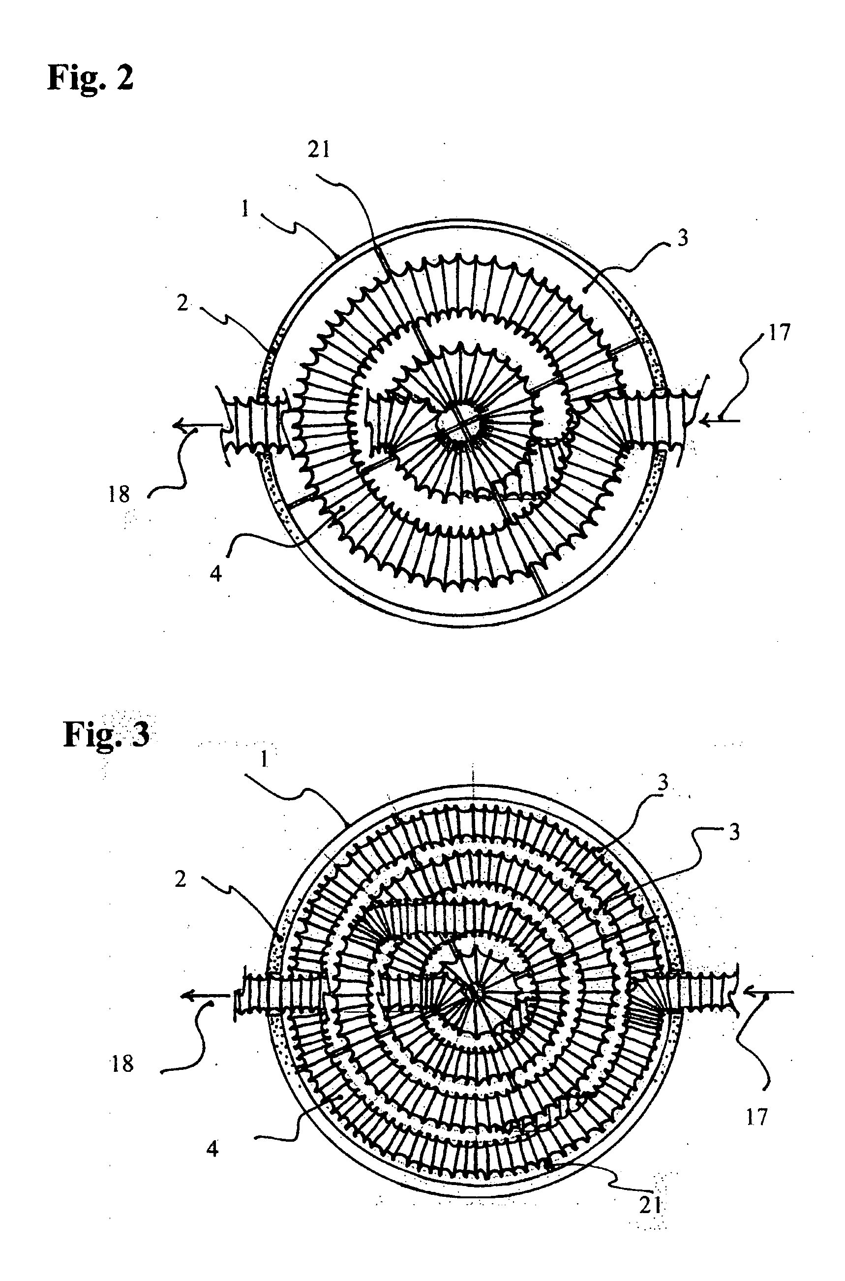
[0033] Referring now to FIG. 1 of the drawings there is shown in sectional view, front elevation, a combustion equipment system including a casing 1, which may be equipped with insulation material 2, defining a primary conduit device 3 designed to enclose a secondary conduit device 4. Said primary conduit device 3 is designed with intake means for the supply of combustion air 5 and fluid hydrocarbon fuel 6 from outside the casing for mixing and ignition in a combustion chamber 7 by way of a burner arrangement 8. The resulting combustion products 11 are routed via the primary conduit device 3 to an exhaust area 9 connected to exit stack 10 outside the casing. The primary conduit device 3, the flow capacity of which is calculated by deducting the space occupied by the secondary conduit device or second energy exchange means 4 from the interior space defined by the casing, must have a flow capacity of at least equal the volume and flow delivery capacity for combustion air 5, in accorda...


PUM


Abstract

A combination of fluid treatment devices operating in unison for the purpose of significantly improving combustion efficiency and energy transfer rate of combustion equipment systems operating with fluid hydrocarbon fuels by significantly increasing the oxygen level in the combustion air / fuel mix from LLE (low level enhancement) to HLE (high level enhancement).

Description

[0001] This invention relates to water storage or flow-through type water heaters, and boilers for hydronic heating systems in domestic, commercial and industrial applications.[0002] Typical water heaters or hydronic boilers in the present art consist of a water storage or water flow-through means, contained in an insulated casing defining a combustion chamber with a burner arrangement and a flue pass to exhaust combustion products.[0003] The flue pass is usually placed through the center of the water storage or water flow-through conduit. Said water conduit is of a very limited surface configuration for the purpose of providing efficient heat transfer from the combustion and flue pass area to the water, and a significant amount of energy is thereby unused and wastefully exhausted. It is important to note that heat transfer efficiency is not only measured in terms of observed flue losses, but must also include the measured energy transfer duration per water volume.[0004] In U.S. Pat...

Claims


Application Information

Patent Timeline
IPC IPC(8): F23D11/44F23D14/66F24H1/43F27B3/20F28D7/02F28F1/08
CPCF23D11/443F23D14/66F24H1/43F28D7/024F28F1/08Y02E20/34
Inventor VELKE, WILLIAM H.
Owner VELKE WILLIAM H
Why Eureka
Try Eureka