
Insufflator and method of use

a technology of insufflator and needle, which is applied in the field of insufflator and method of use, can solve the problems of inability to truly effective prevent internal organ injuries, dismal, and injuring internal organs

Inactive Publication Date: 2004-11-18
ERBLAN SURGICAL
View PDF99 Cites 68 Cited by
  • Summary
  • Abstract
  • Description
  • Claims
  • Application Information

AI Technical Summary

Benefits of technology

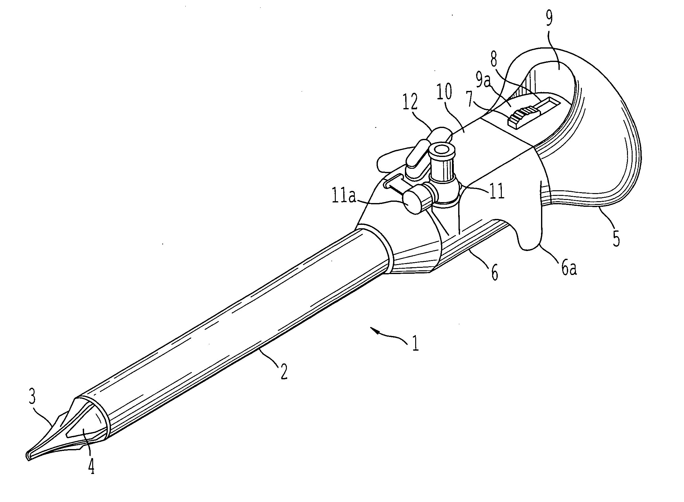
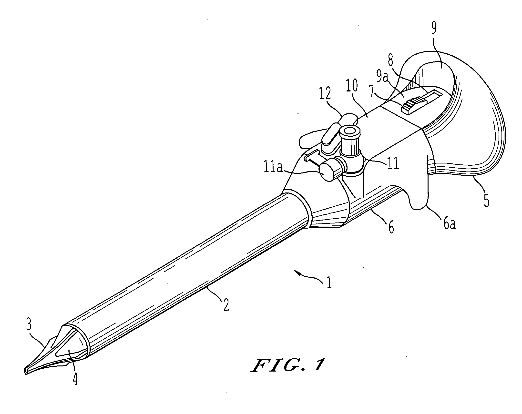
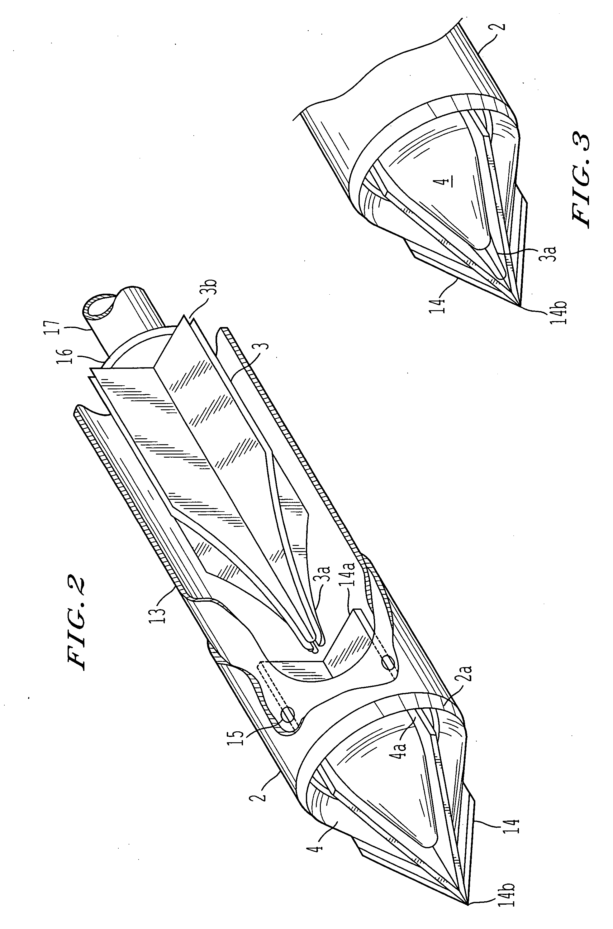
[0008] Accordingly, one object of this invention is to insure that such events be avoided through a surgical device in the form of a trocar or insufflation needle in which a penetrating tip or cutting edge(s) of the instrument be kept, at all times, sufficiently distant from delicate tissues. Thus, even under dynamic conditions, the probability of injury will be reduced.

Problems solved by technology

Most existing trocars or insufflation needles used for endoscopic surgical procedures are incapable of truly effective prevention of injuries to internal organs during insertion and manipulation of the trocar.
Despite intensive efforts to improve present trocar designs, the results are still dismal.
Present procedures frequently injure internal organs, and the resulting wounds are sometimes serious or even fatal.
Such a penetration is fraught with danger of injury to internal organs.
In all cases, however, the designs result in much of the piercing tip being inserted to a dangerous depth before any protecting devices is deployed.
In most cases, however, the force required for penetration and the elastic nature of the muscular layer cause a severe depression at the surgical portal, therefore bringing the penetrating tip of the instrument closer to the internal organs.
Furthermore, friction between the tissue walls and any protective device retards the deployment of the protective device, and an injury almost inevitably occurs.
As mentioned in U.S. Pat. No. 6,497,687 invented by the inventor of the present application, most existing trocars used for endoscopic surgical procedures are incapable of truly effective prevention of injuries to internal organs during insertion and manipulation of the trocar.
Despite intensive efforts to improve present trocar design the results are still dismal.
Present procedures frequently injure internal organs, and the resulting wounds are sometimes serious or even fatal.
Since the locking button is located deep within a recess at the proximal section of the handle, it demands some effort to reach and actuate, and thus it is difficult to accidentally reset.

Method used


Image

  • Insufflator and method of use
  • Insufflator and method of use
  • Insufflator and method of use

Examples


third embodiment

[0088] FIG. 38 shows the distal end of the sleeve of the third embodiment, including the blade.

[0089] FIG. 39 discloses a top plan view of the distal end of the sleeve having a tapered flange.

[0090] FIG. 40 is a top plan view showing the guard when in position in the sleeve;

[0091] FIG. 41 shows a side view of an additional embodiment of the present invention; and

[0092] FIG. 42 shows a side view of the cannula and blade thereof.

[0093] In one embodiment, fluid is delivered into and through the device from an appropriate tubing or syringe via a Luer lock coupler 101 and is flow controlled with a simple stopcock mechanism 102, both items being common and well-known in the industry.

[0094] The outer body of the device is a hollow cylinder 104 (possibly made of surgical steel) and which is contemplated as being of a diameter of 1.0-4.0 mm in the preferred embodiment, to which is fixed a distal cutting blade 104a. Within the outer body cylinder resides a coaxial sliding spring-loaded cylind...

first embodiment

[0101] A further embodiment of the invention is designed to increase the dilating forces of the outer sleeve 204 by the addition of a larger surface area at the distal end 210c (FIG. 33). This larger surface area may be created by thickening the wall of the outer sleeve. The proximal extent of this thickened wall is denoted as 210f. Although the inner guard lumen is somewhat narrowed, it is still adequate for the passage of fluids 210e. The cutting edge 204a is of the same relative geometry to the sliding inner guard as the first embodiment, but the cutting blade, itself, may be made as a solid, flat piece of metal without an internal window 204b. The line denoted 210b (FIG. 39) shows the proximal extent of this cutting blade. The blade may be securely fixed the outer sleeve at the area denoted 210d.

second embodiment

[0102] The sliding inner guard of the second embodiment retains the same relative geometry to the cutting edge as described earlier in the invention. The most distal tip 212a of the guard may have a semi-conical shape, convex to the outside (FIG. 34). The guard tip 212a may also be of a more squared shape, depending on its application. The flow of fluid through the tip of the device is augmented by greatly enlarging the defect in the guard tip and reducing the support of the guard tip to two bilateral, parallel rails or posts. The ample communication between the inner guard lumen and large guard defects is demonstrated in the rotated axial side view of the sliding inner guard tip. The distal extent of the defect is denoted by the line 213a (FIG. 35).

[0103] A side axial view of the assembled an additional embodiment is shown (FIG. 34). When the guard is fully extended, it is apparent that there is ample space through the distal tip for the flow of fluid 212b, yet there is a large are...


PUM


Abstract

A surgical device and method for endoscopic surgical procedures capable of preventing injuries to internal organs during insertion. The surgical device can include one or more of the following: a multiple system of sharp blade edges or a single blade, a mechanical tissue protection device that includes a series of thin plastic guards sliding along the sides of the planar knives and having an angle between their edges smaller than that of the cutting knife edges, one or more fixed conical deflectors to expand the cut tissue passage leaving the guards to contact tissue contact only at their tips, an insufflation passage configured to transport fluid into the body cavity during penetration, a locking system for the guards that prevents accidental reuse of the cutting features, and / or an ergonomic design which facilitates handling.

Description

[0001] This application claims priority to, and is a continuation-in-part of, U.S. application Ser. No. 10 / 324,050, filed on Dec. 20, 2002, currently allowed, which is a continuation application of application Ser. No. 09 / 598,453, issued as U.S. Pat. No. 6,497,687; which claims the benefit of priority to provisional application Ser. No. 60 / 140,409, filed Jun. 22, 1999 and also claims priority to provisional application No. 60 / 452,040, filed on Mar. 6, 2003, and provisional application No. 60 / 494,122, filed on Aug. 12, 2003, each to Blanco, the disclosures of which are incorporated by reference herein in their entireties.DESCRIPTION OF THE INVENTION[0002] An insufflator is a needle-like device through which a gas or other fluid can be injected into a space or potential space somewhere within the body. The device and the method of use thereof is not limited to use in humans. Indeed, the device could find applications in numerous unrelated fields where precise penetration of embedded s...

Claims


Application Information

Patent Timeline
IPC IPC(8): A61B17/00A61B17/34
CPCA61B17/3417A61B17/3474A61B17/3494A61B17/3496A61B2017/00544A61B2017/346
Inventor BLANCOWILSHIRE, GILBERT B.
Owner ERBLAN SURGICAL
Learn More