
Image-forming apparatus

a technology of image-forming apparatus and charging roller, which is applied in the direction of electrographic process apparatus, instruments, corona discharge, etc., can solve the problems of easy contamination of charge roller, degraded charging performance, and unpleasant ozone smell

Inactive Publication Date: 2004-11-11
CANON KK
View PDF2 Cites 16 Cited by
  • Summary
  • Abstract
  • Description
  • Claims
  • Application Information

AI Technical Summary

Benefits of technology

[0016] Another object of the present invention is to provide an image-forming apparatus which prevents contamination of a rotating charging member.
[0019] Another object of the present invention is to provide an image-forming apparatus in which a potential difference between the image carrier and the charging member is controlled.

Problems solved by technology

However, this device operates at a high voltage, and therefore inevitably produces an unpleasant ozone smell.
In addition, this device includes a corona discharge unit, which is relatively large and requires a high-voltage power source.
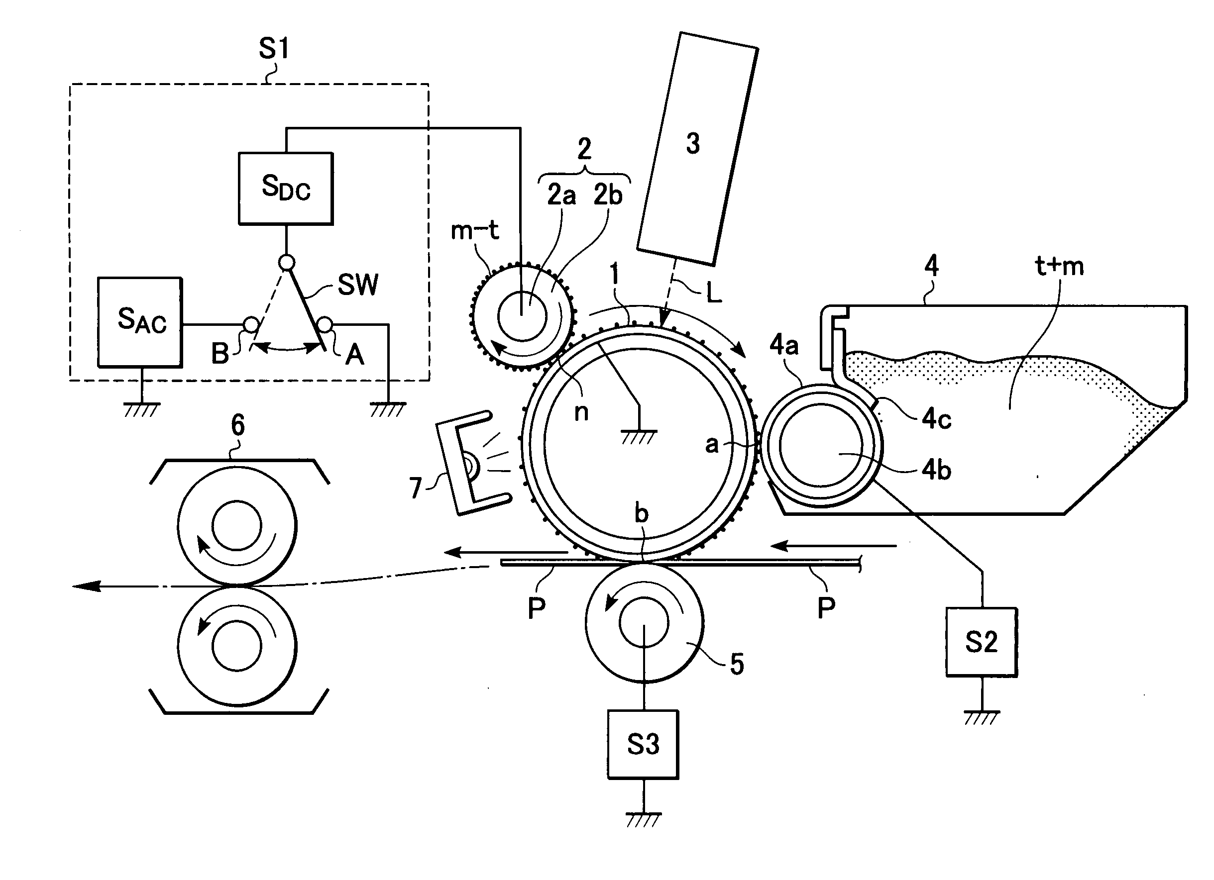
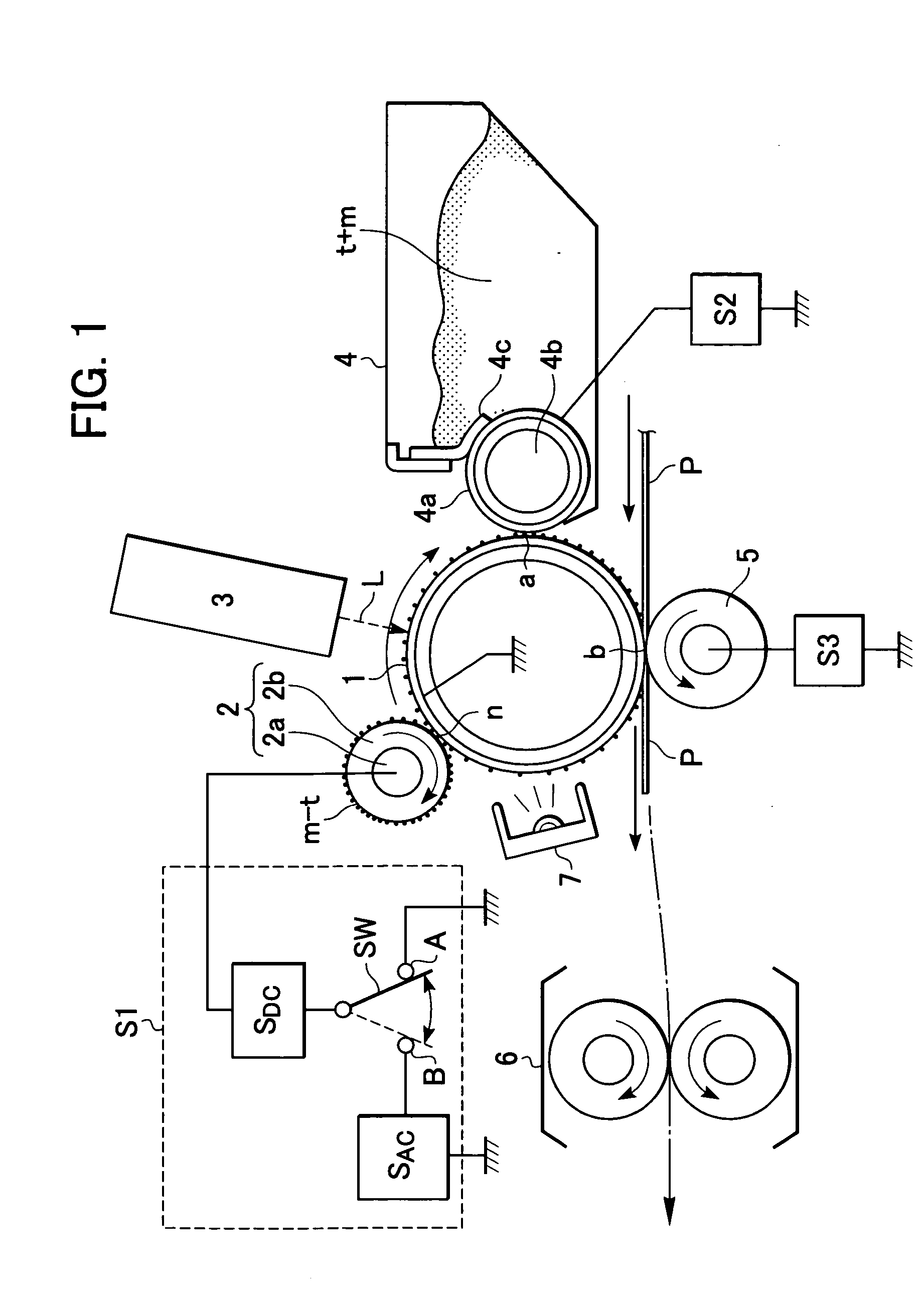
In these image-forming apparatuses, however, the charge roller often picks up substances like the residual toner adhering to the photoconductor since it is in contact with the surface of the photoconductor to charge the surface of the photoconductor, and therefore the charge roller is easily contaminated.
When the charge roller is excessively contaminated, uniform charging cannot be achieved and the charging performance is degraded.
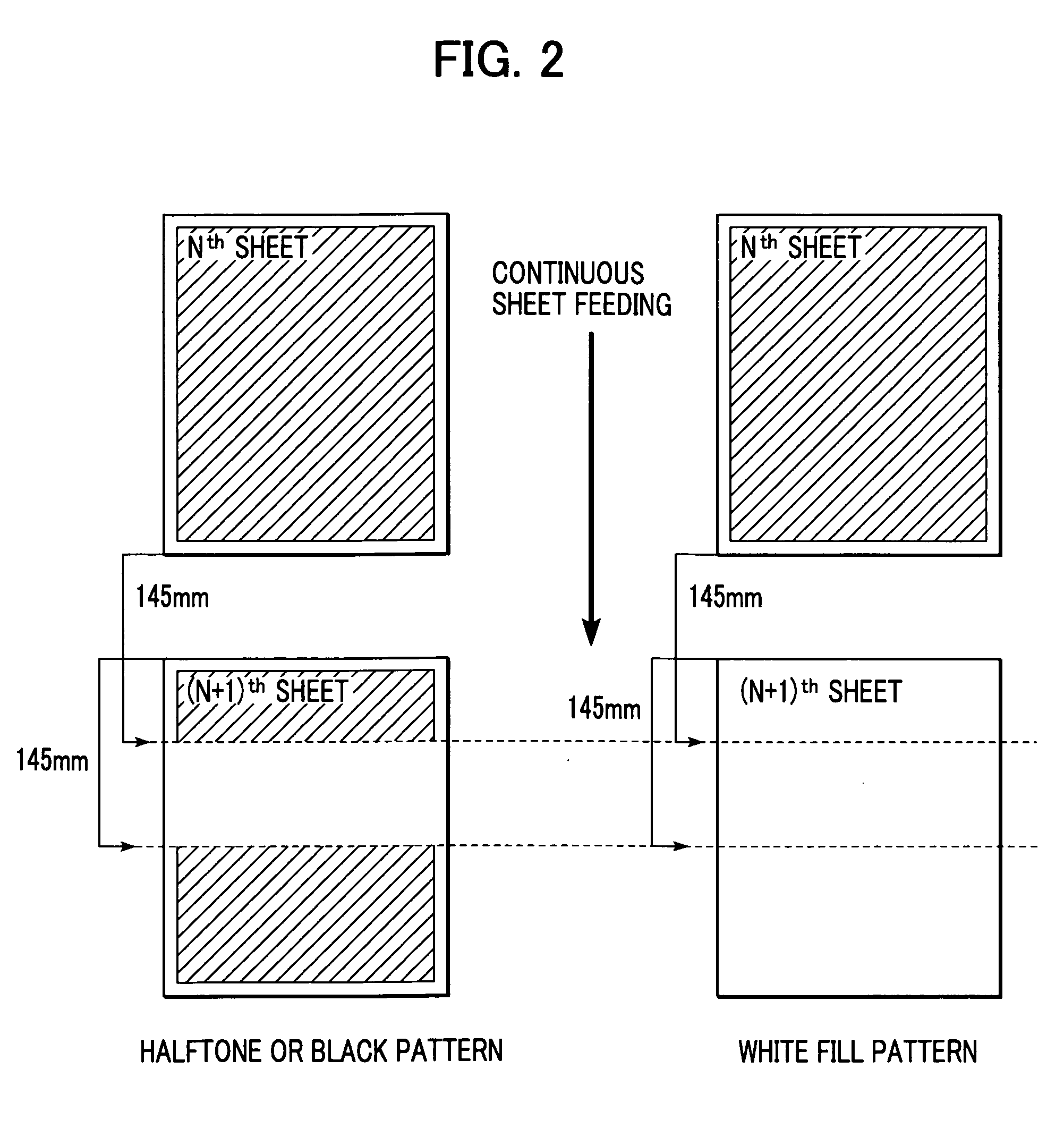
When the residual toner accumulating in the nip region is discharged while an image is being formed, it will block exposure if it is in a black or halftone region of a graphic pattern or the like and causes an image defect.
In addition, if the discharged toner is in a white region, it causes other kinds of image defects such as fogging.
Since the toner t is normally insulative, there is a risk that the toner t adhering to the charge roller 2 will cause charge failure.
As a result, the driving torque becomes too high and there is a risk that the surfaces of the charge roller 2 and the photoconductor drum 1 will be damaged if the charge roller 2 is forcedly rotated.
In addition, the contact stability cannot be sufficiently increased by the charge-accelerating particles m, and satisfactory charging performance cannot be obtained.
In contrast, when the amount of the charge-accelerating particles m in the nip region n is too large, the charge-accelerating particles m easily falls off the charge roller 2 and cause adverse effects on the image being formed.
If the number of the charge-accelerating particles m is less than 103 per square millimeters, sufficient lubricating effect and the effect of increasing the contact stability cannot be obtained, and the charging performance is degraded.
Normally, these image defects normally occur when continuous sheet feeding is performed and appear on the second or the following recording sheets in a band shape.
The thus discharged toner blocks the laser beam if it is in a region to be exposed, and the latent image cannot be formed in such a case.
This leads to a defect called light-blocking, which leaves white dots on the recording sheet.
Although the discharged toner does not block the laser beam if it is in a white-fill region, which is outside the region to be exposed, there is a risk that it cannot be completely collected in the development step.

Method used


Image

  • Image-forming apparatus
  • Image-forming apparatus
  • Image-forming apparatus

Examples


Embodiment Construction

Good Good Good Good

[0126] As is clear from Table 1, the second comparative example and the embodiment are more effective in preventing light-blocking and fogging than the first comparative example when the continuous sheet feeding is performed. In particular, light-blocking and fogging are extremely effectively prevented in the embodiment, and dot not occur even after a large number of sheets have been processed.

[0127] Although light-blocking and fogging in the second and the following sheets in the continuous sheet-feeding operation are mainly discussed above, the present invention is not limited to this. For example, according to the present invention, light-blocking and fogging can also be prevented in the case in which the residual toner is adhered to the charge roller before the start of the printer operation and the potential applied in pre-print rotation is low.

[0128] As described above, the potential changing means (pre-charge exposure device) changes the potential differenc...


PUM


Abstract

An image-forming apparatus includes a pre-charge exposure device which removes electric charge from a photoconductor drum to increase a potential contrast between the surface of the photoconductor drum and the surface of a charge roller in an upstream region of a nip region between the photoconductor drum and the charge roller in the rotating direction of the photoconductor drum, so that toner accumulating in an upstream region of the nip region in the rotating direction of the photoconductor drum is restrained and prevented from being discharged onto an image-forming region. When the toner accumulating in the upstream region of the nip region in the rotating direction of the photoconductor drum is to be discharged onto a non-image-forming region, the pre-charge exposure device is turned off so that the potential contrast decreases.

Description

[0001] 1. Field of the Invention[0002] The present invention relates to image-forming apparatuses, such as copy machines and printers, and more specifically relates to an image-forming apparatus which uses a contact charge method and a transfer method and performs a toner-recycling process.[0003] 2. Description of the Related Art[0004] A typical image-forming apparatus performs an electrophotography process including the basic steps of charging, exposure, development, transfer, and fixing. More specifically, a charging device uniformly charges the surface of a rotating photoconductor and an exposure optical system irradiates the charged surface of the rotating photoconductor so as to form an electrostatic latent image on the photoconductor. The electrostatic latent image moves toward a development section as the photoconductor rotates, and is developed by a development device so that a developer image (toner image) is formed on the photoconductor. Then, the toner image is conveyed t...

Claims


Application Information

Patent Timeline
IPC IPC(8): G03G21/14G03G15/02G03G15/08G03G21/08
CPCG03G15/0225G03G2221/0005
Inventor NAKAHARA, HISASHICHIGONO, YASUNORINAKATA, YASUHIRO
Owner CANON KK
Learn More