
Exercise weight system

a weight system and exercise technology, applied in the field of exercise devices, can solve the problems of difficult balance and control, damage to the plate and storage rack, and dangerous handling

Inactive Publication Date: 2004-10-07
LANDFAIR CRAIG D
View PDF8 Cites 7 Cited by
  • Summary
  • Abstract
  • Description
  • Claims
  • Application Information

AI Technical Summary

Problems solved by technology

Inherent to most weight training equipment is the fact that they are bulky, difficult to balance and control, and dangerous to handle as the amount of weight increases since users handling them can easily lose control and drop the devices, especially when they have exercised for a while and are fatigued.
Dumbbells and barbells are therefore often used in a rough manner, and commonly dropped or banged against the storage racks, damaging their plates and the storage rack.
This method of storage is not space efficient because saddles must be evenly spaced on the tray rack, and each saddle must have the same bulky size.
A further, more fundamental disadvantage inherent in such a storage method is the use of the dumbbell head or weight plates for the storage.
Rough handling the dumbbells by dropping them may damage the rack saddles and may damage the head or weight plates when they hit the rack tray.

Method used


Image

  • Exercise weight system
  • Exercise weight system
  • Exercise weight system

Examples


Embodiment Construction

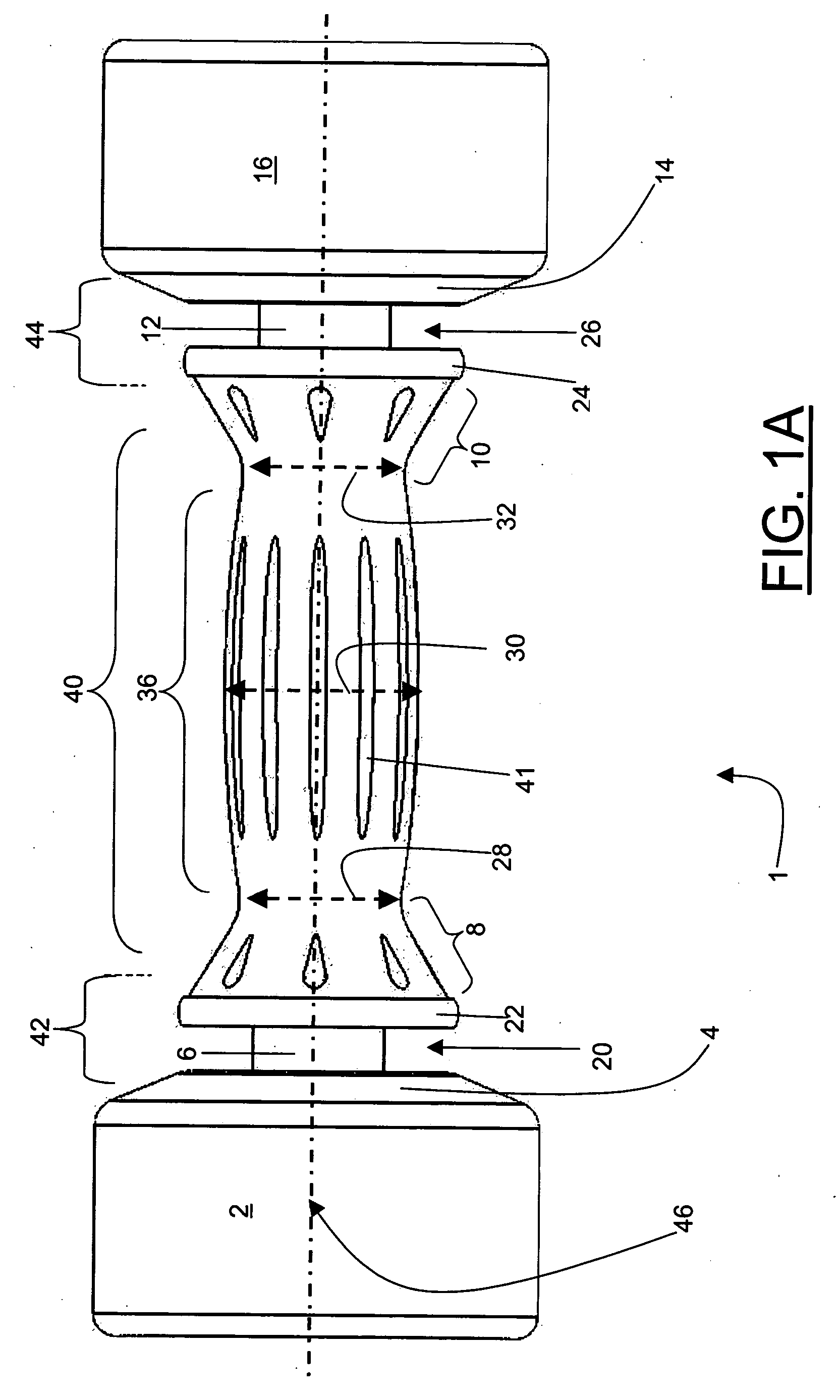
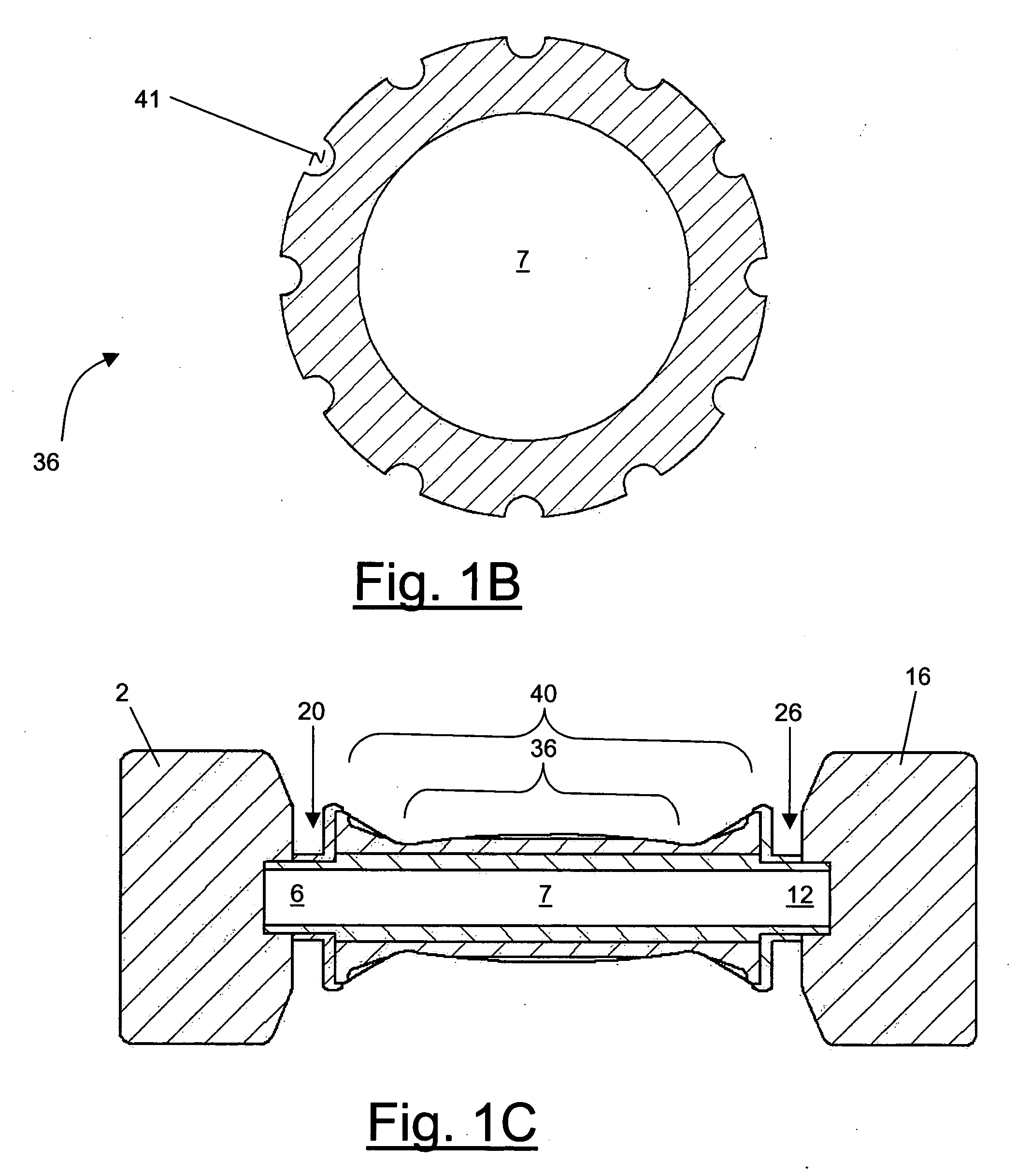
[0023] FIG. 1 is an exemplary illustration of an inertial force exercise device 1 with dense body extremities 2 and 16 in accordance with the present invention. As illustrated, the exercise device 1 comprises of an approximately cylindrical ergonomic snug grip handle bar 40. The handle 40 comprises a middle portion 36 and two edge grip end portions 8 and 10 that are contiguous with and uniformly integral part of the middle portion 36. The diameter of the middle portion 36 at section 30, moving towards the proximal ends of the two edge grip portions 8 and 10, at sections 28 and 32, respectively, gradually decreases. Thereafter, beyond the proximal sections 28 and 32, the diameter of the handle 40 increases at the distal ends of the portions 8 and 10 as illustrated. The diameters of the two distal ends of the portions 8 and 10 are graduated to meet at near the top of the respective collars 22 and 24 of the device 1.

[0024] This innovative construction method for the handle 40 requires ...


PUM


Abstract

The present invention uses an inertial force exercise device comprised of an ergonomically snug grip handle bar, racking collars on either side of the handle including head plates in combination with a storage racking system that enables appropriate mating with the racking collars of the inertial force exercise device. The racking collars are comprised of a circumferential groove that mate with a "U" shaped spaces or openings on the racking storage unit. This way, the outer surfaces of the dense extremities of the exercise device are not exposed to the rack to become damaged. The invention therefore isolates the outer surfaces on the dense extremities of the exercise device from physically contacting the storage rack. The storage system is also space efficient because the slots need not be configured to accommodate the largest size dense extremity, but only the racking collars of the exercise device.

Description

[0001] The present application claims priority from related U.S. Provisional patent application Ser. No. 60 / 417,451, filed Oct. 10, 2002, the entire disclosure of which is incorporated herein by reference.[0002] 1) Field of the Invention[0003] The present invention relates generally to exercise devices, and in particular to devices used for weight training and weight lifting, such as dumbbells, barbells, and their respective storage racks.[0004] 2) Description of Related Art[0005] Dumbbells and barbells are inertial force exercise devices with dense body extremities. They comprise of a central handle bar for griping the devices, with weight heads or plates attached at or near either end of the bar. In general, the heads may comprise of removable circular weight plates so that different or additional weight heads may be attached as desired to vary the weight of the device. Dumbbells and barbells with non-removable weight heads or plates comprise of circular weight plates permanently ...

Claims


Application Information

Patent Timeline
IPC IPC(8): A63B21/072A63B71/00
CPCA63B21/0726A63B71/0036
Inventor LANDFAIR, CRAIG D.
Owner LANDFAIR CRAIG D
Learn More