Control device

a control device and control technology, applied in the direction of electrically conductive connections, coupling device connections, electrical apparatus, etc., can solve the problem of extremely economic production of control devices, and achieve the effect of reducing the complexity of the technical valve features necessary for installation

Active Publication Date: 2004-10-07
FESTO AG & CO KG
View PDF5 Cites 3 Cited by
  • Summary
  • Abstract
  • Description
  • Claims
  • Application Information

AI Technical Summary

Benefits of technology

[0003] One object of the invention is to provide a control device of the type initially mentioned, in the case of which the complexity of the technical valve features necessary for the installation is reduced.
[0005] The control device now renders it possible to selectively and interchangeably mount at one and the same component mounting area an electrical connection module or an electrically operated fluid control module equipped with an electrically operated valve means. The control device may possess several identical component mounting areas, which respectively are able to carry either a connection module or a fluid control module so that the control device may be extremely adaptably modified as regards the technical requirements in an individual case. Since for the fluid control module no separate component mounting area is necessary, the production of the control device is extremely economic. Moreover it is an advantage that the fluid control module not only possesses fluid line connections permitting the connection of at least one load but also at least one further fluid line connection by way of which through a fluid line fluid coming from a pressure source may be introduced so that the base of the control device itself does not require any internal fluid ducts. In addition there is the possibility, in the case of the simultaneous installation of a plurality of fluid control modules, to provide for a mutually independent operation of such fluid control modules each having a different operating pressure.
[0007] Preferably a plurality of preferably identical component mounting areas are provided on the base each having a first electrical central interface which are able to selectively carry a connection module or a fluid control module. The component mounting areas are preferably arranged in a row direction one after the other in sequence and in a common plane of extent. The latter feature means convenient fitting in place and removal of the individual modules from the same side.

Problems solved by technology

Since for the fluid control module no separate component mounting area is necessary, the production of the control device is extremely economic.

Method used


Image

  • Control device
  • Control device

Examples


Embodiment Construction

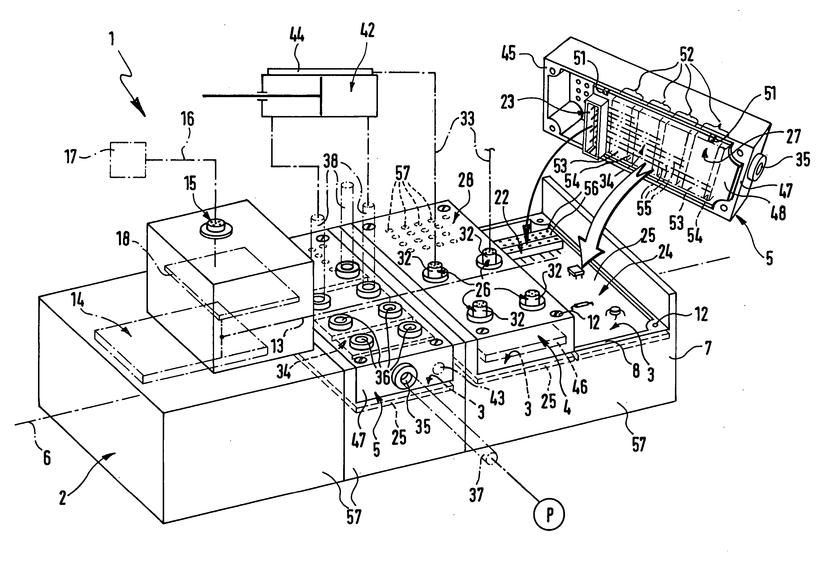
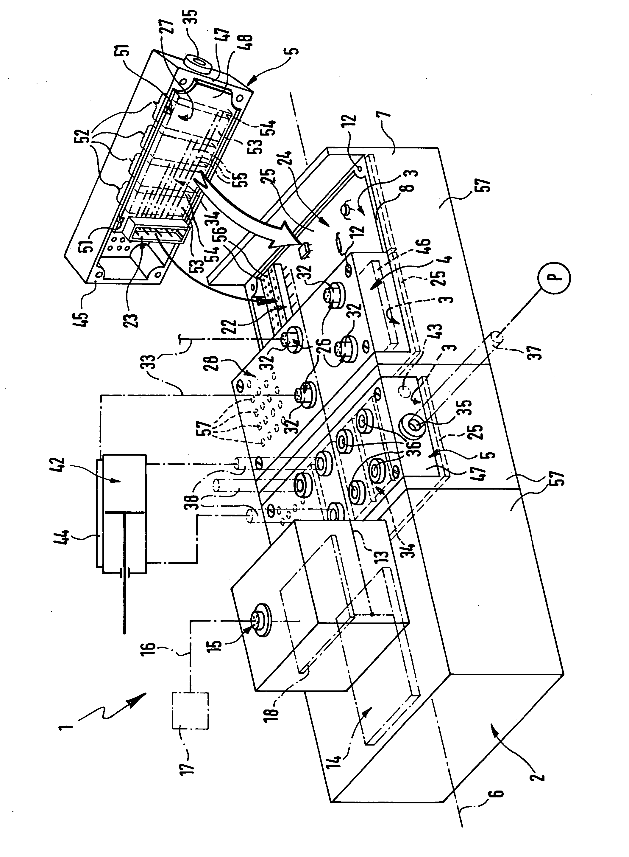
[0015] The control device generally referenced 1 comprises a base 2, on which a plurality of component mounting areas 3 are provided, on which selectively an electrical connection module 4 or an electrically control fluid control module 5 are able to be mounted temporarily, i.e. detachably. In the working embodiment the base 2 is provided with in all three component mounting areas 3, one thereof bearing an electrical connection module 4, a further one bearing a fluid control module 4 and the third component mounting area 3 being unoccupied so far and a second fluid control module 5 is depicted just in the course of being installed on the third component mounting area 3.

[0016] The base 2 of the working embodiment has an elongated shape with a principal axis 6 extending in the longitudinal direction. The component mounting areas 3 are identical in design and are arranged in a row direction running in the direction of the principal axis 6 on the base. The component mounting areas 3 are...


PUM


Abstract

A control device having a base which is provided with one or more component mounting areas. On each component mounting area there is a first electrical central interface connected with an internal electrical bus. On each component mounting area an electrical connection module or an electrically controlled fluid control module may be selectively mounted, which respectively has a second central interface complementary to the first electrical central interface. The fluid control module is provided with a valve means, which is controlled by signals supplied by means of the internal electrical bus. The connection modules are provided with inputs and / or outputs for the connection of electrical cables.

Description

[0001] The invention relates to control device comprising a base, on which at least one component mounting area is provided, which is equipped with a first electrical central interface connected with an internal electrical bus extending in the base, and at least one electrical connection module having electrical inputs and / or outputs permitting a temporary connection of electrical cables, which lead away from the control device, such connection module being able to be mounted on the at least one component mounting area and having a second electrical central interface adapted, as regards the mounting and removal of the electrical connection module, to automatically make contact and, respectively, interrupt contact with respect to the first electrical central interface.THE PRIOR ART[0002] A known control device disclosed in the patent publication WO 01 / 42664 A2 of this type has on a longitudinal side several identical component mounting areas on a base, which are each equipped with a ...

Claims


Application Information

Patent Timeline
IPC IPC(8): F15B13/00F15B13/08
CPCF15B13/0814F15B13/0832F15B13/0853F15B13/0857F15B13/0867F15B13/0892F15B13/0896F15B2013/006F15B13/0825
Inventor GRAFF, UWEWIRTL, HANNES
Owner FESTO AG & CO KG
Why Eureka
Try Eureka