
Release device

a technology of release device and release plate, which is applied in the direction of snap fasteners, buckles, belt retractors, etc., can solve the problems of high manufacturing cost, high risk of disturbance of operation, and complicated structure of the buckle according to u.s. pat. no. 4,815,177

Inactive Publication Date: 2004-10-07
JOHANSSON MALTE
View PDF2 Cites 16 Cited by
  • Summary
  • Abstract
  • Description
  • Claims
  • Application Information

AI Technical Summary

Benefits of technology

[0004] A primary object of the present invention is to disclose a release device of the type defined above, said device being structurally extremely simple.
[0006] Still an object of the present invention is to give the release device a compact design, especially as regards the automatic release function.

Problems solved by technology

There is no doubt that the buckle according to U.S. Pat. No. 4,815,177 is structurally extremely complicated and hence also expensive to manufacture.
By having a number of components to cooperate there is also a risk of disturbances in operation.
Also this buckle is structurally extremely complicated and due to its complicated structure it is also relatively seen voluminous.

Method used


Image

  • Release device
  • Release device
  • Release device

Examples


Embodiment Construction

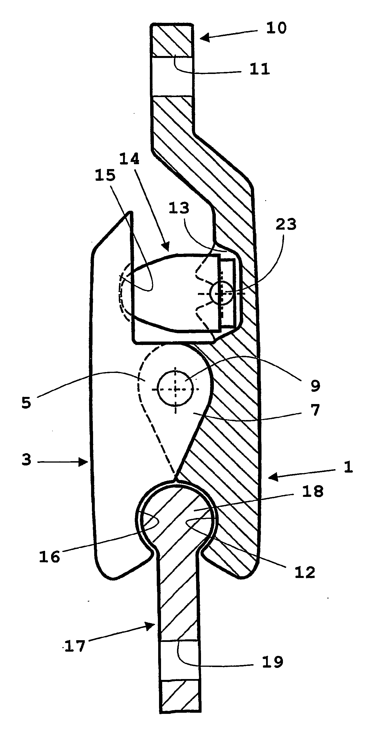
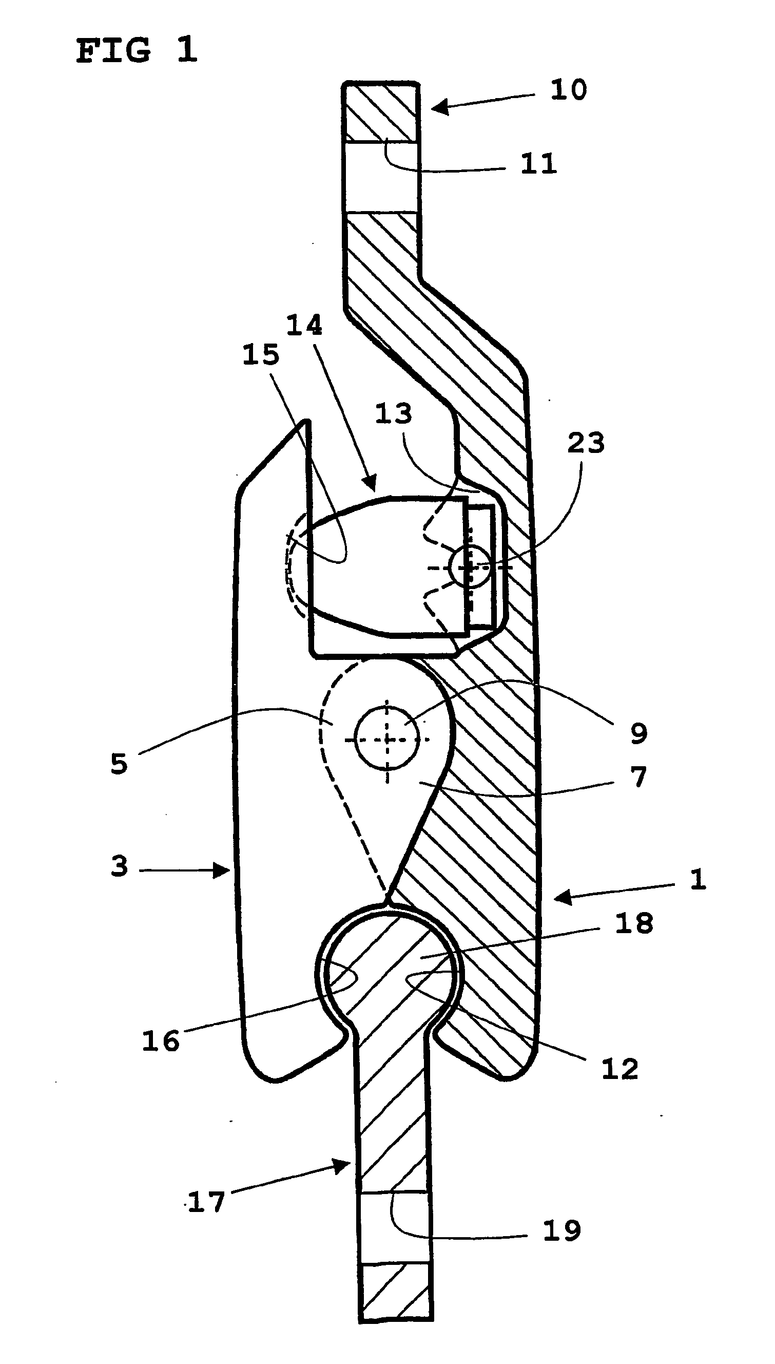
[0012] The release device shown in FIG. 1 comprises a first element 1 and a second element 3, each of said elements 1, 3 being equipped with an eye 5 and 7 respectively, said eyes 5, 7 being mutually connected by means of a hinge 9. This means that the elements 1 and 3 are hingedly connected to each other, i.e. the elements may pivot relative to each other around said hinge 9.

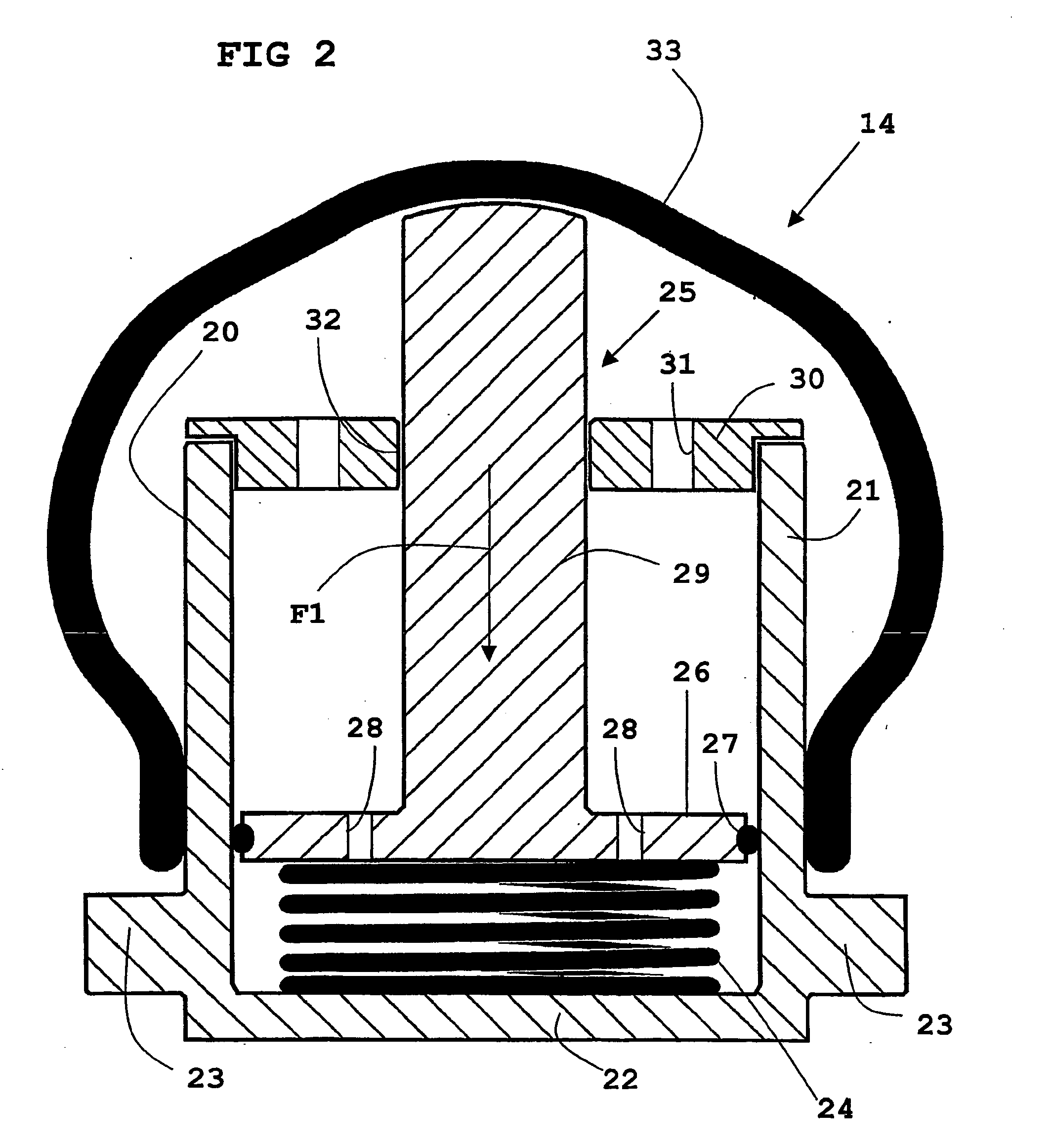
[0013] The first element 1 has generally an elongated shape and has at one end a first attachment portion 10 that is equipped with a first hole 11 for anchoring of one end of a strap / belt (not shown). In the area of its other end the first element 1 has a first recess 12 that in the shown embodiment has a curved shape. In an intermediate portion the first element 1 has a first depression 13 that in the shown embodiment constitutes a seat of a release means 14 that constitutes a portion of the release device according to the present invention, said release means 14 being fixed in the depression 13. The release m...


PUM


Abstract

The present invention relates to a release device, especially in relation to a buckle of a safety helmet or a safety belt. It is significant of the release device according to the present invention that the device comprises a first element (1) and a second element (3) that are pivotally connected to each other via a hinge (9), means (10) of one element (1) to connect one end of the strap / belt, a yieldable release means (14) and an anchoring element (17) connected to the other end of the strap / belt, that the anchoring element (17) is connected in a releasable way to the elements (1, 3), and that a force (F1) is applied to the release means (14) when the anchoring element (17) is subjected to force (F2) that strives to separate the anchoring element (17) from the elements (1, 3).

Description

[0001] The present invention relates to a release device, especially in relation to a buckle of a safety helmet or a safety belt.PRIOR ART[0002] From U.S. Pat. No. 4,815,177 a buckle of a safety belt is previously known, said buckle will open after a certain time delay in connection with a collision. In connection therewith a spring must initially be released, this being effected by applying an exceptional force to the belt, e.g. in connection with a collision. Thereafter, a yoke, included in the buckle, will be urged downwards by two main springs and the yoke affects levers that effects release of the belt at one side of the buckle. In order to prevent that this is not happening too fast the movement of the yoke is counteracted by a time delay unit that includes pressurised bellows. There is no doubt that the buckle according to U.S. Pat. No. 4,815,177 is structurally extremely complicated and hence also expensive to manufacture. By having a number of components to cooperate there ...

Claims


Application Information

Patent Timeline
Patent Type & Authority Applications(United States)
IPC IPC(8): A44B11/25
CPCA44B11/2592Y10T24/45461A42B3/08A44B11/2526
Inventor JOHANSSON, MALTE
Owner JOHANSSON MALTE
Learn More