
Capacitive humidity sensor

a humidity sensor and capacitive technology, applied in the direction of variable capacitors, instruments, using mechanical means, etc., can solve the problems of troublesome countermeasures, offsetting voltage, and deterioration of humidity detection accuracy

Inactive Publication Date: 2004-09-23
DENSO CORP
View PDF22 Cites 34 Cited by
  • Summary
  • Abstract
  • Description
  • Claims
  • Application Information

AI Technical Summary

Benefits of technology

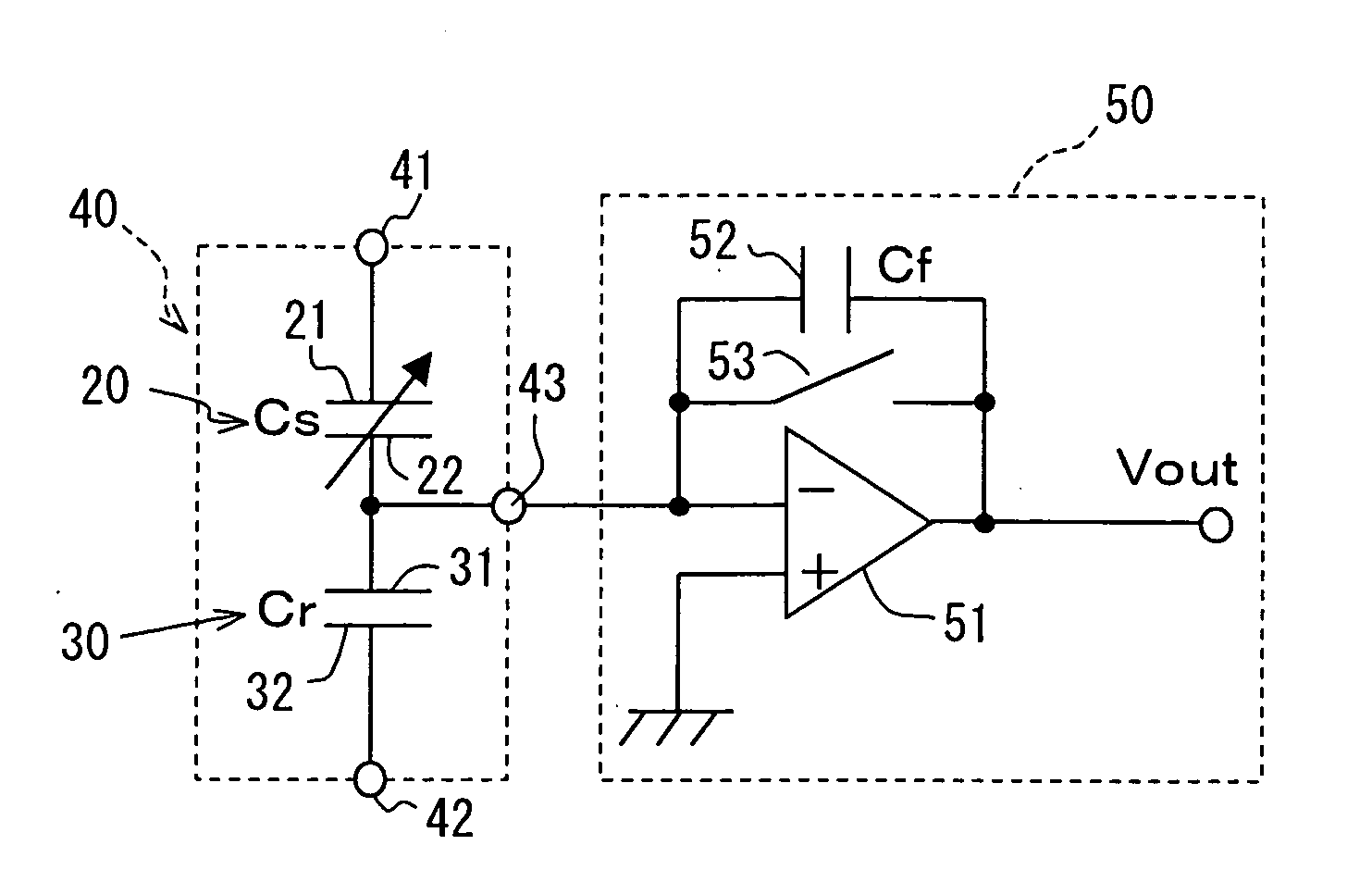
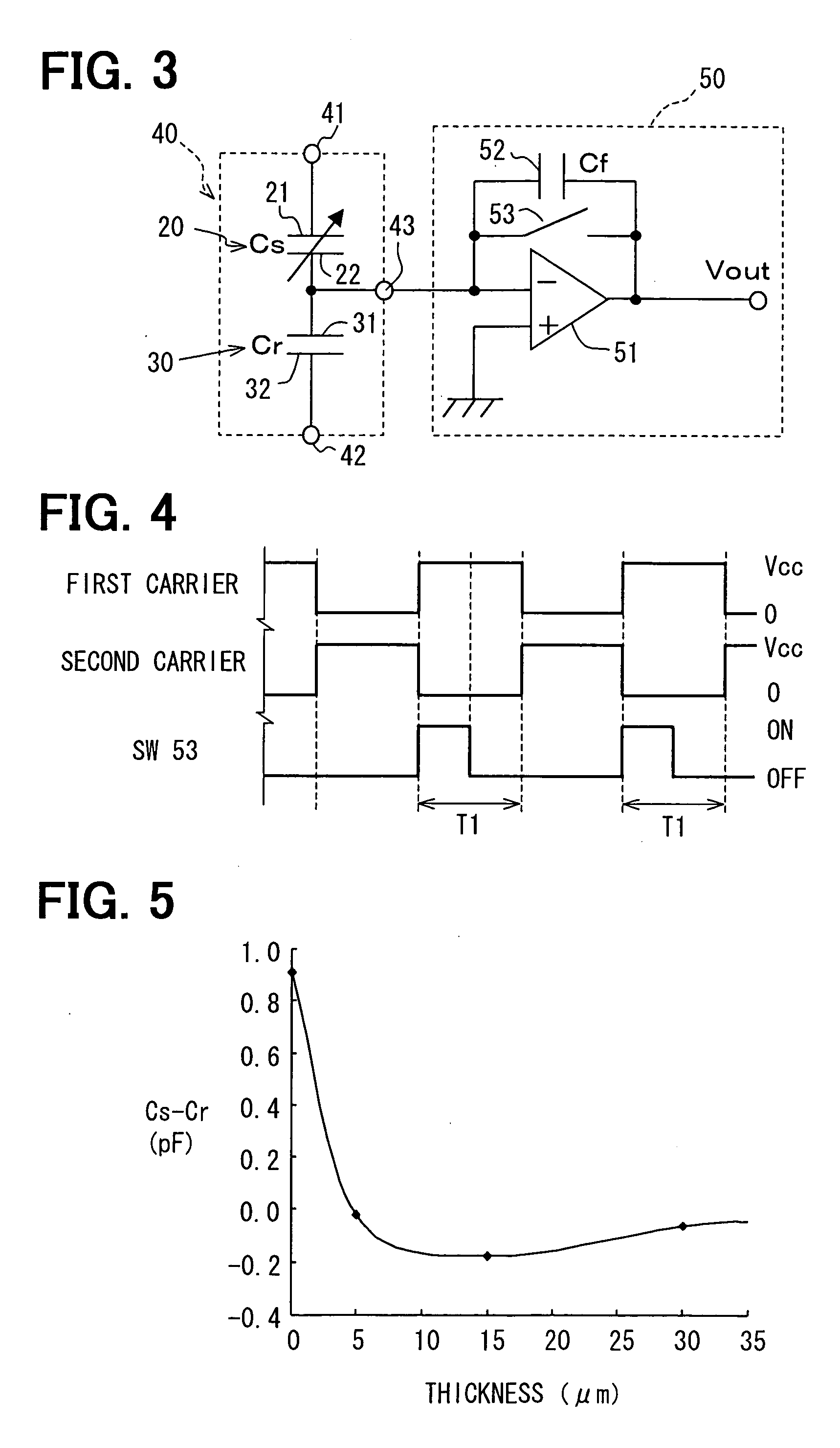
The present invention relates to a capacitive humidity sensor that can reduce offset voltage and can be reduced in size. The sensor includes a detection portion and a reference portion. The reference portion has a reference electrode and a wiring electrode, and a capacitance adjusting film is provided on the reference electrodes to reduce the offset voltage. This film helps to reduce the difference in capacitance between the detection electrodes and the reference electrodes when humidity is in a reference humidity condition. The sensor does not require an offset compensation circuit or the enlarging of the pattern of the reference electrodes, which makes it easier to reduce size.

Problems solved by technology

This causes offset voltage.
As a result, accuracy of humidity detection deteriorates.
However, troublesome countermeasures are required in order to reduce the offset voltage in this capacitive humidity sensor.
Further, it is difficult to reduce size of the sensor because an area where the circuit element portion is formed is enlarged.

Method used


Image

  • Capacitive humidity sensor
  • Capacitive humidity sensor
  • Capacitive humidity sensor

Examples


first embodiment

[0022] (First Embodiment)

[0023] A capacitive humidity sensor according to the first embodiment is used for detecting indoor humidity for a humidity control of an air conditioner, detecting outdoor humidity for weather observation or the like.

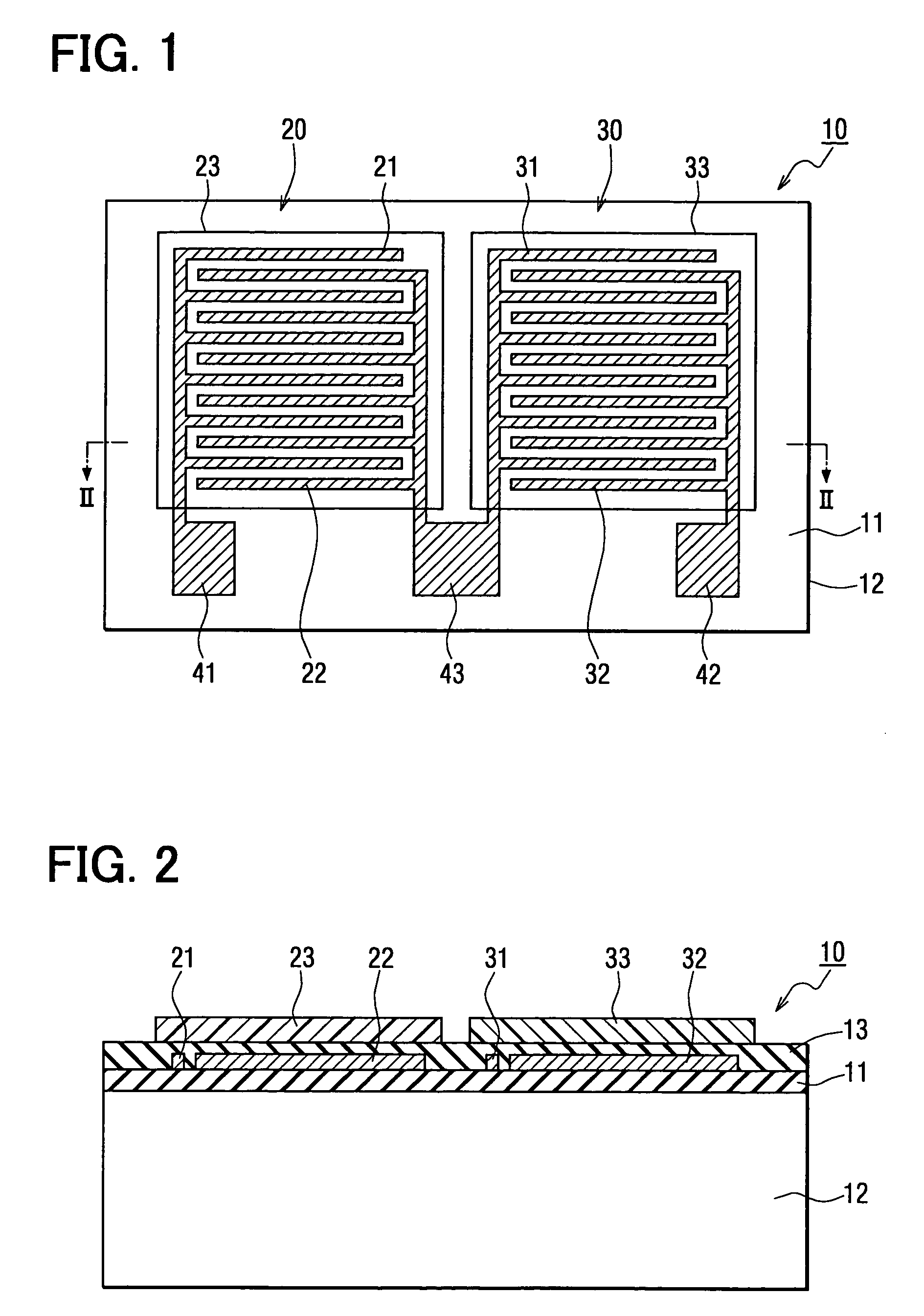
[0024] In a capacitive humidity sensor 10 shown in FIGS. 1 and 2, a first insulation film 11 is formed on a semiconductor substrate 12. A sensor portion is formed on the first insulation film 11. The sensor portion includes a detection portion 20 and a reference portion 30. The capacitive humidity sensor 10 detects humidity based on a difference between a capacitance of the detection portion 20 and a capacitance of the reference portion 30.

[0025] The semiconductor substrate 12 is made of single crystal silicon or the like. A silicon oxide film is formed as the first insulation film 11 on the surface of the semiconductor substrate 12. Furthermore, a pair of detection electrodes 21, 22, which oppose each other, is formed on the first insulation fi...

second embodiment

[0056] (Second Embodiment)

[0057] In the first embodiment, the moisture permeation film 33 is used as the capacitance adjusting film. However, in the second embodiment, the moisture sensitive film 23 and a moisture blocking film are formed as the capacitance adjusting film instead of the moisture permeation film 33.

[0058] As shown in FIG. 7, the detection electrodes 21, 22 and the reference electrodes 31, 32 are formed on the same plane. The silicon nitride film is formed as the second insulation film 13 on these electrodes 21, 22, 31, 32. The patterns of both the detection electrodes 21, 22 and the reference electrodes 31, 32 are substantially equal. In a region of the sensor portion 40 on the second insulation film 13, that is, a region of the detection portion 20 and the reference portion 30, the moisture sensitive film 23 which is made of polyimide or the like is formed.

[0059] Accordingly, the capacitance Cs of the detection portion 20 at 0% RH and the capacitance Cr of the refer...


PUM

PropertyMeasurementUnit
RHaaaaaaaaaa
RHaaaaaaaaaa
RHaaaaaaaaaa

Abstract

A capacitive humidity sensor includes a detection portion and a reference portion. The detection portion includes detection electrodes and a moisture sensitive film. The reference portion includes reference electrodes and a moisture permeation film as a capacitance adjusting film. The capacitive humidity sensor detects humidity by converting a capacitance difference between a capacitance of the detection electrodes and a capacitance of the reference electrodes to an electric signal by using a capacitance-voltage conversion circuit. The moisture permeation film reduces offset voltage of the capacitive humidity sensor. Thus, an offset compensation circuit or the like is not required.

Description

[0001] This application is based on Japanese Patent Application No. 2003-75017 filed on Mar. 19, 2003, the disclosure of which is incorporated herein by reference.[0002] 1. Field of the Invention[0003] The present invention relates to a capacitive humidity sensor, which has a capacitance adjusting film in a reference portion in order to reduce offset voltage of the sensor.[0004] 2. Description of Related Art[0005] A capacitive humidity sensor, which detects humidity based on a change of capacitance between two detection electrodes provided on a semiconductor substrate, is disclosed in U.S. Pat. No. 6,580,600 B2 (corresponding to JP-A-2002-243690).[0006] This sensor has two detection electrodes, which oppose each other, on a first insulation film formed on a surface of a semiconductor substrate. The detection electrodes are covered with a second insulation film and are further covered with a moisture sensitive film thereon. In addition, a reference portion, having a reference capacit...

Claims


Application Information

Patent Timeline
Patent Type & Authority Applications(United States)
IPC IPC(8): G01N27/22
CPCG01N27/225
Inventor HAMAMOTO, KAZUAKI
Owner DENSO CORP
Learn More