
Power controller of combined electronic equipment

a technology of power controller and electronic equipment, which is applied in the direction of process and machine control, instruments, television systems, etc., can solve the problems of needing useless power consumption by that amount, and increasing the cost of the equipment by that amount, so as to reduce the need for useless power consumption and simple configuration

Inactive Publication Date: 2004-09-16
ORION ELECTRIC CO LTD
View PDF5 Cites 2 Cited by
  • Summary
  • Abstract
  • Description
  • Claims
  • Application Information

AI Technical Summary

Benefits of technology

[0010] Aiming at the supply of power having a plurality of different levels to the functional blocks for every functional block in the combined electronic equipment, the stop of supply of power is controlled, thereby surely holding down useless power consumption with a simple configuration.

Problems solved by technology

By integrally combining the electronic equipment with one another, electronic equipment per se can be made downsized compared with a case where each electronic equipment is provided as a single unit, thereby attaining a merit capable of transmitting information at a high speed between the electronic equipment, but there is a case where power is supplied to the electronic equipment such as DVDs and so forth which are not used even when only TVs and VCRs are used, which causes a problem that useless power consumption is needed by that amount.
However, according to the foregoing prior art technical references, an output of the power supply per se is the same as in the past while a power supply line to a circuit block is shut off, and hence the output of the power supply portion is not stopped, thereby generating useless power consumption by that amount.
Further, it is necessary to add a new circuit configuration such as switches and so forth for shutting off the power supply, thereby increasing cost thereof by that amount.

Method used


Image

  • Power controller of combined electronic equipment
  • Power controller of combined electronic equipment
  • Power controller of combined electronic equipment

Examples


Embodiment Construction

[0015] The embodiment of the invention is now described in detail. Since the embodiment set forth hereunder is preferable concrete example to carry out the invention, they are technically restricted variously but the invention is not limited to the embodiment unless specifically describing that the invention is limited.

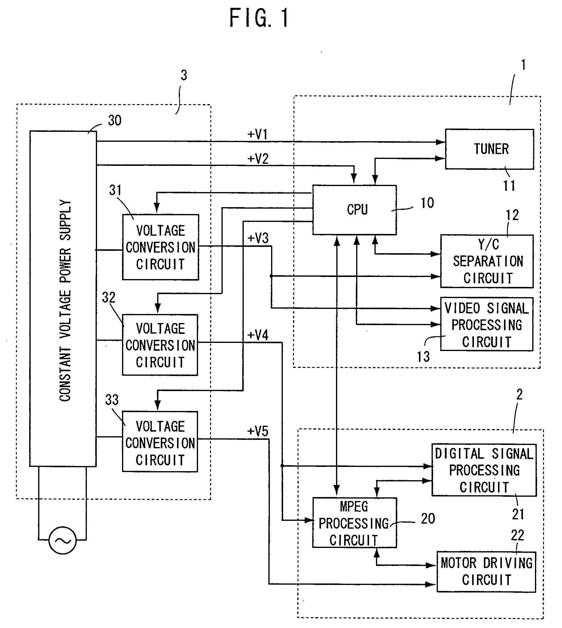
[0016] FIG. 1 is a schematic block diagram of a combined electronic equipment of a TV, a VCR and a DVD provided with the embodiment of the invention. This block diagram shows a portion of a circuit to which power is supplied so as to facilitate the understanding of the invention. Depicted by 1 surrounded by the dotted line is a block relating to a TV and a VCR, by 2 surrounded by the dotted line is a block relating to a DVD. Depicted by 3 surrounded by the dotted line is a power supply portion for supplying power to these blocks.

[0017] Provided in the block 1 are circuits corresponding to functional blocks such as a body CPU 10 for controlling an entire combined elect...


PUM

PropertyMeasurementUnit
voltagesaaaaaaaaaa
voltagesaaaaaaaaaa
power supplyaaaaaaaaaa

Abstract

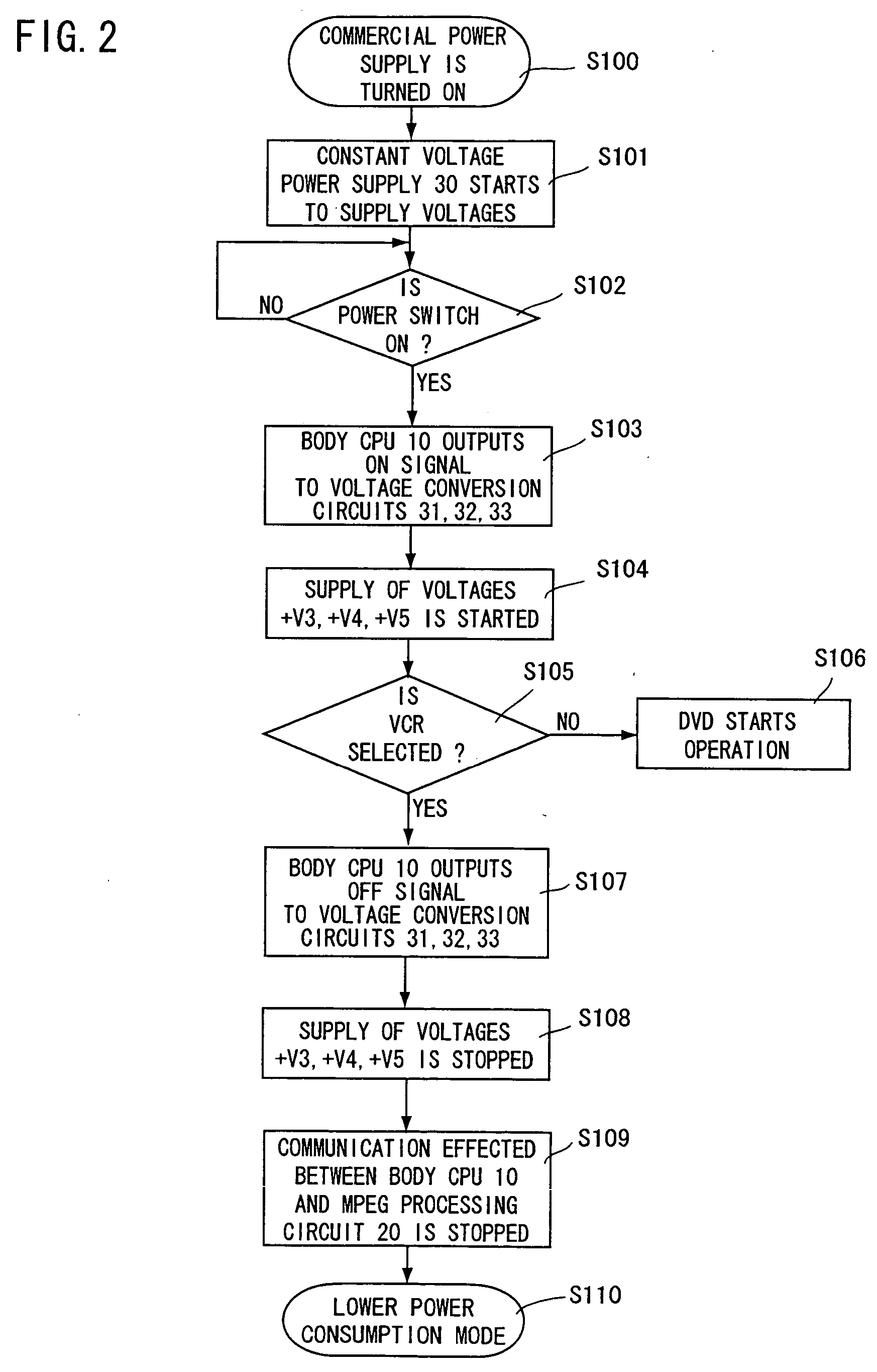
An object of the invention is to provide a power supply controller for stopping an output of a power supply portion without adding a new circuit in the combined electronic equipment, and dispensing with ON / OFF operation of a power supply each time for every electronic equipment. The supply of power is controlled by supplying a control signal from a body CPU to voltage conversion circuits for supplying voltages having different levels to corresponding functional blocks, and the voltage conversion circuit for supplying a voltage having a level corresponding to a non-used functional block is controlled to be turned OFF, thereby reducing power consumption.

Description

[0001] 1. Field of the Invention[0002] The invention relates to a power supply controller of a combined electronic equipment formed by integrally combining equipment with one another such as TVs (televisions), VCRs (Video Cassette Recorders), DVDs (Digital Versatile Discs including its recording / reproducing unit), HDDs (Hard Disk Drivea) and so forth.[0003] 2. Description of Related Art[0004] Electronic equipment formed by integrally combining electronic equipment associated with image information with one another such as TVs, VCRs, DVDs, HDDs and so forth has recently come into practical use. By integrally combining the electronic equipment with one another, electronic equipment per se can be made downsized compared with a case where each electronic equipment is provided as a single unit, thereby attaining a merit capable of transmitting information at a high speed between the electronic equipment, but there is a case where power is supplied to the electronic equipment such as DVDs...

Claims


Application Information

Patent Timeline
Patent Type & Authority Applications(United States)
IPC IPC(8): G06F1/26G06F1/32G11B19/00G11B31/00H02J1/00H02M3/335H04N5/63H04N5/85H04N9/804
CPCG11B19/00G11B31/00H02M1/36H02M3/33561Y02B70/16H02M2001/0032H04N5/63H04N5/85H04N9/8042H02M2001/0012Y02B70/10H02M1/0012H02M1/0032
Inventor OKUMURA, YOSHIHIRO
Owner ORION ELECTRIC CO LTD
Learn More