
Surface acoustic wave actuator and deflector employing the same

a deflector technology, applied in piezoelectric/electrostrictive/magnetostrictive devices, piezoelectric/electrostriction/magnetostriction machines, instruments, etc., can solve the problem of limiting the application range of the surface acoustic wave actuator, generating only small force, and hardly providing large deflection angles

Active Publication Date: 2004-07-15
RAKUTEN GRP INC
View PDF5 Cites 15 Cited by
  • Summary
  • Abstract
  • Description
  • Claims
  • Application Information

AI Technical Summary

Problems solved by technology

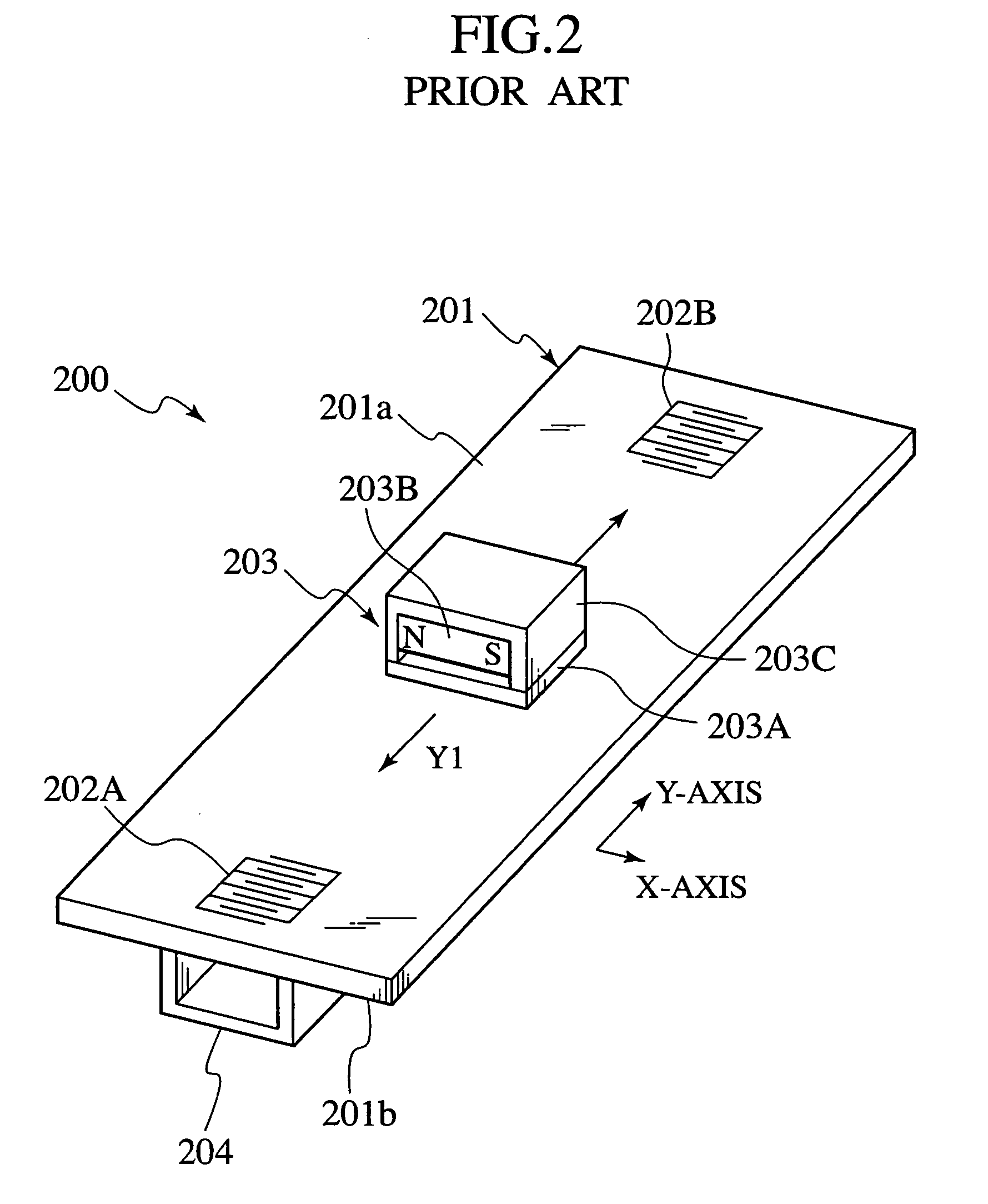
This raises a problem of limiting a range of applications of the surface acoustic wave actuator 200.
The former, however, generates only small force and hardly provides large deflection angles.
Accordingly, power consumption will increase when keeping a fixed deflection angle for a certain extent of time.
As a result, no power is consumed to maintain the deflecting face of the deflector at a given inclination angle, and therefore, the deflector as a whole consumes little power.

Method used


Image

  • Surface acoustic wave actuator and deflector employing the same
  • Surface acoustic wave actuator and deflector employing the same
  • Surface acoustic wave actuator and deflector employing the same

Examples


Embodiment Construction

[0043] Embodiments of a surface acoustic wave actuator and a deflector employing the same according to the present invention will be explained in detail item by item with reference to FIGS. 3A to 12.

[0044]

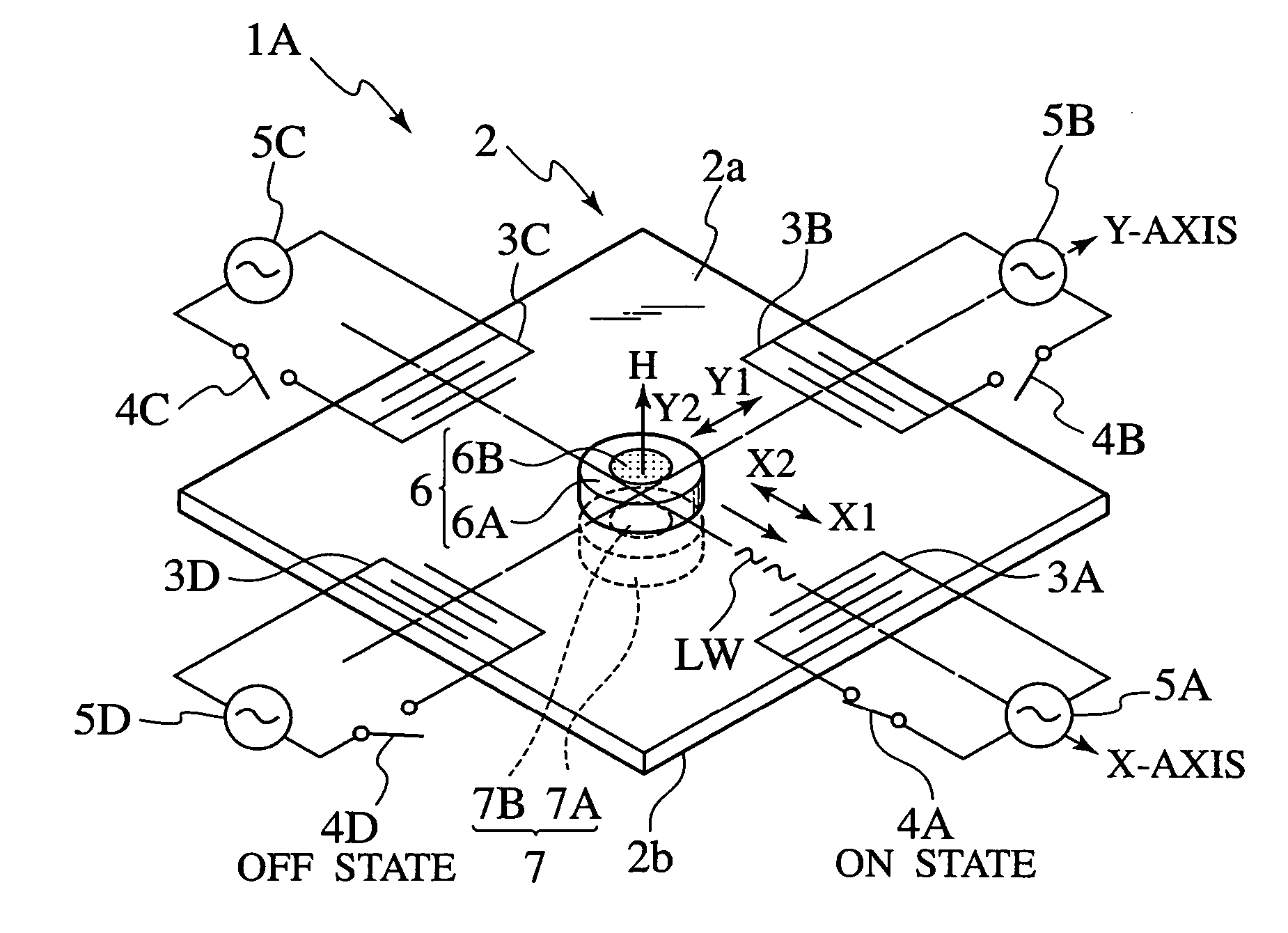
[0045] FIGS. 3A and 3B are a perspective view and a sectional view taken along an X-axis showing a surface acoustic wave actuator according to an embodiment of the present invention.

[0046] In FIGS. 3A and 3B, the surface acoustic wave actuator 1A according to an embodiment of the present invention has a piezoelectric board 2 made of, for example, lithium niobate and having a square shape. A first surface or a top surface 2a of the piezoelectric board 2 is a two-dimensional X-Y plane defined by an X-axis and a Y-axis that is orthogonal to the X-axis.

[0047] On the X-axis at right and left ends of the top surface 2a of the piezoelectric board 2, comb-shaped electrodes 3A and 3C are formed. On the Y-axis at upper and lower ends of the top surface 2a, comb-shaped electrodes 3B and 3D a...


PUM


Abstract

A surface acoustic wave actuator has a mover arranged on a first surface of a piezoelectric board and comb-shaped electrodes formed on the first surface. High frequencies are applied to the comb-shaped electrodes to generate Rayleigh waves that move the mover. In the surface acoustic wave actuator, the com-shaped electrodes include first to fourth electrodes formed on the first surface of the piezoelectric board, the first and third comb-shaped electrodes being on each side of the mover on an X-axis, the second and fourth comb-shaped electrodes being on each side of the mover on a Y-axis. The mover at least has a permanent magnet. The surface acoustic wave actuator further has a unit to selectively apply a high frequency to at least one of two electrodes one selected from the first and third comb-shaped electrodes and the other from the second and fourth comb-shaped electrodes. The surface acoustic wave actuator also has a mover holder facing the mover with the piezoelectric board interposed therebetween. The mover holder at least has a magnetic material configured to hold the mover.

Description

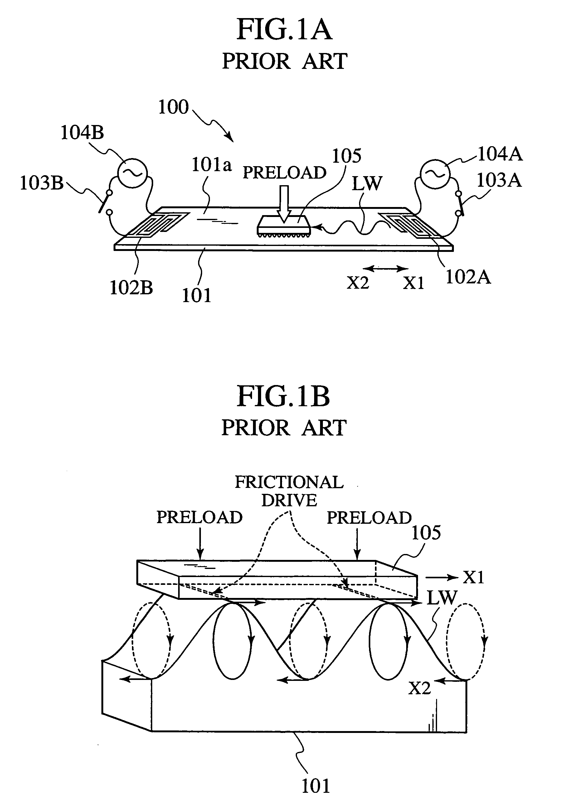
[0001] 1. Field of the Invention[0002] The present invention relates to a surface acoustic wave actuator and a deflector employing the same.[0003] 2. Description of Related Art[0004] Surface acoustic wave actuators generally demonstrate excellent working performance such as high speed, high thrust, and high resolution, and due to this, they are actively researched and developed for linear actuators, etc.[0005] FIGS. 1A and 1B are perspective views explaining a surface acoustic wave actuator according to a related art 1, in which FIG. 1A schematically shows the structure of the surface acoustic wave actuator (or motor) and FIG. 1B shows a concept of frictional drive by Rayleigh waves.[0006] In FIG. 1A, the surface acoustic wave actuator 100 of the related art 1 is developed as, for example, a surface acoustic wave motor. The surface acoustic wave actuator 100 has a piezoelectric board 101 made of, for example, lithium niobate and having a rectangular shape. At right and left ends on ...

Claims


Application Information

Patent Timeline
IPC IPC(8): H02N2/00G02B26/08H10N30/20
CPCG02B26/0858H02N2/0055H02N2/08H02N2/046H02N2/028
Inventor ISEKI, TAKAYUKI
Owner RAKUTEN GRP INC
Learn More