Rectilinear ion trap and mass analyzer system and method

Active Publication Date: 2004-07-15
PURDUE RES FOUND INC
View PDF2 Cites 135 Cited by
  • Summary
  • Abstract
  • Description
  • Claims
  • Application Information

AI Technical Summary

Benefits of technology

0007] It is a general object of the present invention t

Problems solved by technology

All of the above ion traps, except the cylindrical ion trap, require accurate mechanical processing such as machi

Method used


Image

  • Rectilinear ion trap and mass analyzer system and method
  • Rectilinear ion trap and mass analyzer system and method
  • Rectilinear ion trap and mass analyzer system and method

Examples


Embodiment Construction

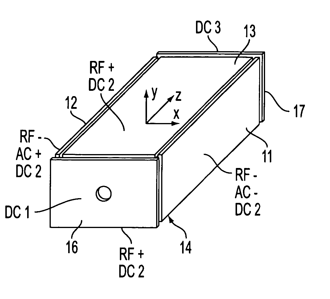
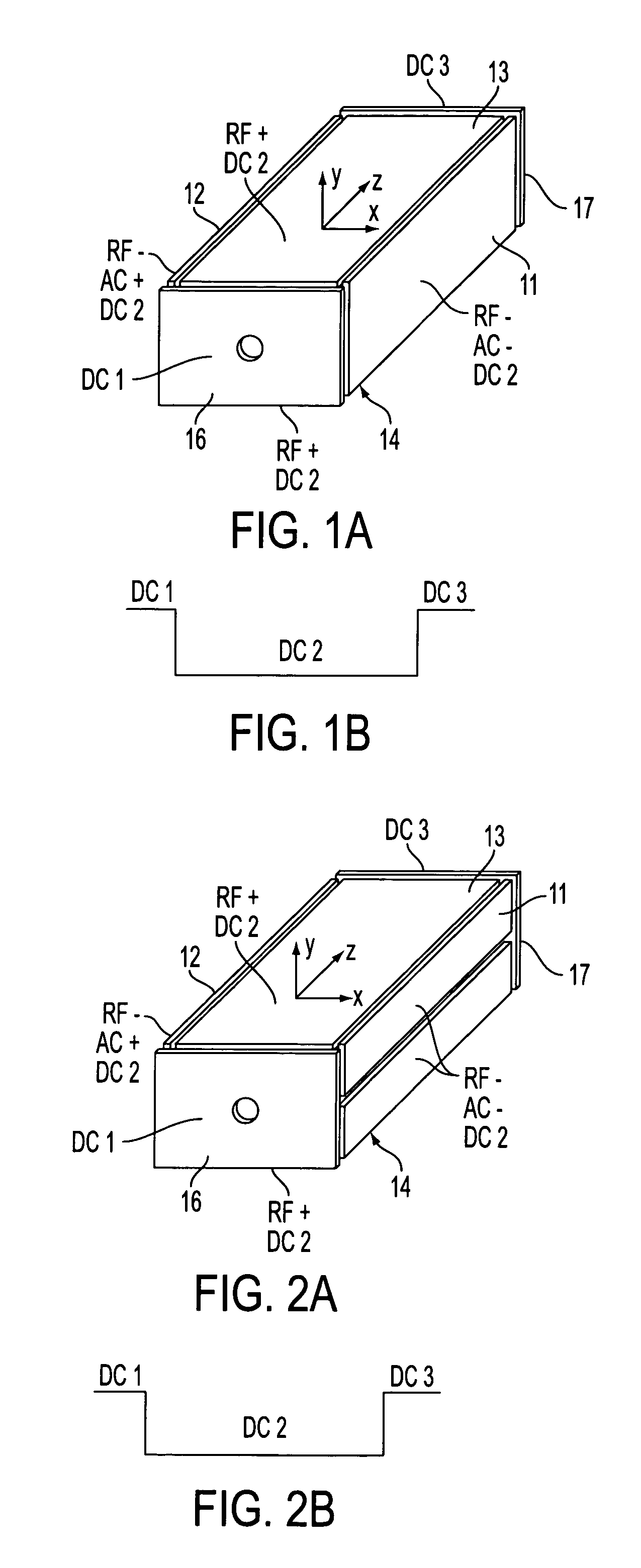
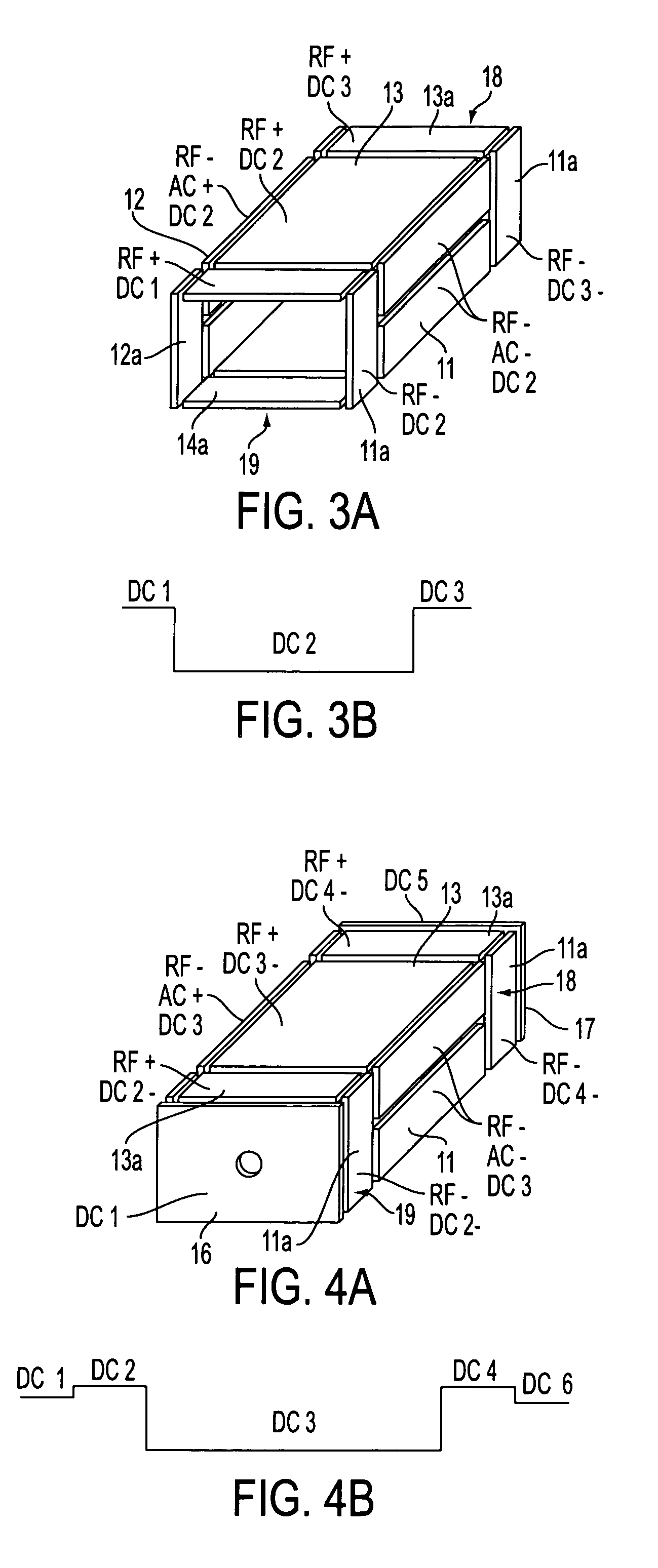
[0041] FIGS. 1-4 illustrate four rectilinear ion trap geometries and the DC, AC and RF voltages applied to the electrode plates to trap and analyze ions as the case may be. The trapping volume is defined by x and y pairs of spaced flat or plate RF electrodes 11, 12 and 13, 14 in the zx and zy planes. Ions are trapped in the z direction by DC voltages applied to spaced flat or plate end electrodes 16, 17 in the xy plane disposed at the ends of the volume defined by the x, y pair of plates, FIGS. 1 and 2, or by DC voltages applied together with RF in sections 18, 19 each comprising pairs of flat or plate electrodes 11a, 12aand 13a, 13b, FIG. 3. In addition to the RF sections flat or plate electrodes 16, 17 can be added, FIG. 4. The DC trapping voltages are illustrated in FIGS. 1b, 2b, 3b and 4b for each geometry. The ions are trapped in the x, y direction by the quadrupolar RF fields generated by the RF voltages applied to the plates. As will be presently described, ions can be ejecte...


PUM


Abstract

A new geometry ion trap and its use as a mass spectrometer is described. The ion traps can be combined linearly and in parallel to form systems for mass storage, analysis, fragmentation, separation, etc. of ions. The ion trap has a simple rectilinear geometry with a high trapping capacity. It can be operated to provide mass analysis in the mass-selective instability mode as well as the mass-selective stability mode. Arrays of multiple ion traps allow combinations of multiple gas-phase processes to be applied to the trapped ions to achieve high sensitivity, high selectivity and/or higher throughput in the analysis of ions.

Description

[0001] This application claims priority to provisional application Serial No. 60 / 439,350 filed Jan. 10, 2003.[0002] The present invention relates generally to an ion trap and an ion trap mass analyzer and more particularly to a rectilinear ion trap and mass analyzer employing a rectilinear ion trap.[0003] Three-dimensional ion traps with quadrupolar fields in both the r and z (in a polar coordinate system) direction impose linear forces on ions and can be used as traps for ions of wider or narrower ranges of mass / charge values. The field shapes are usually provided by a set of three electrodes, a ring electrode and two end cap electrodes of hyperbolic shape. Such devices are known as a Paul or quadrupole ion traps. In simpler alternative devices, the cylindrical ion traps (CITs), the inner surface of the ring is cylindrical and the end caps are flat.[0004] The Paul trap and the cylindrical ion trap have known deficiencies. They include limits on the number of ions that can be trappe...

Claims


Application Information

Patent Timeline
IPC IPC(8): G01NH01J49/42
CPCH01J49/422
Inventor OUYANG, ZHENGCOOKS, ROBER T G.
Owner PURDUE RES FOUND INC
Why Eureka
Try Eureka