
Exhaust system of image forming device

a technology of exhaust system and image forming device, which is applied in the direction of cooling/ventilation/heating modification, printers, instruments, etc., can solve the problems of image formation problems, reducing the number of fans in the image forming device, and reducing the efficiency of cooling the power source circuit board

Active Publication Date: 2004-05-20
BROTHER KOGYO KK
View PDF12 Cites 41 Cited by
  • Summary
  • Abstract
  • Description
  • Claims
  • Application Information

AI Technical Summary

Problems solved by technology

However, along with the recent trend of manufacturing smaller, quieter image forming devices, the number of fans mounted in the image forming device is decreased, reducing the efficiency of cooling the power source circuit board.
Further, when the power source circuit board is disposed near other circuit boards, other components, or the like, heat generated from the power source circuit board is transferred to the other circuit boards, other components, and the like, causing problems in image formation.

Method used


Image

  • Exhaust system of image forming device
  • Exhaust system of image forming device
  • Exhaust system of image forming device

Examples


Embodiment Construction

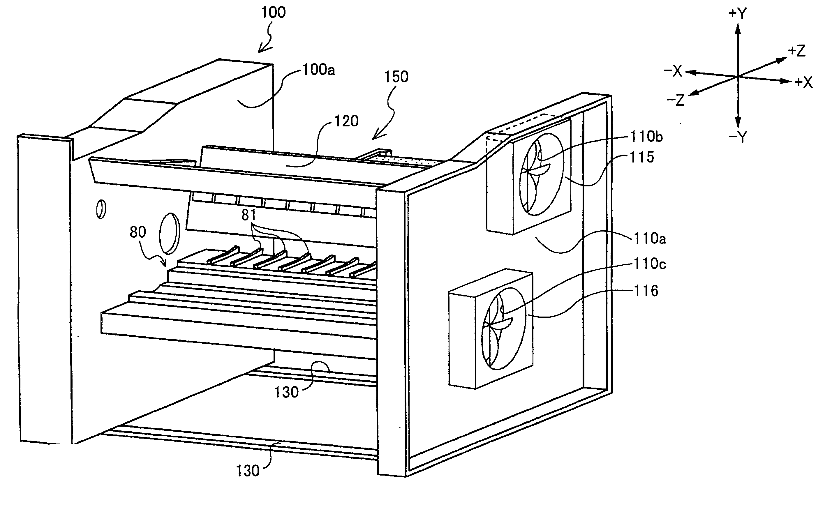
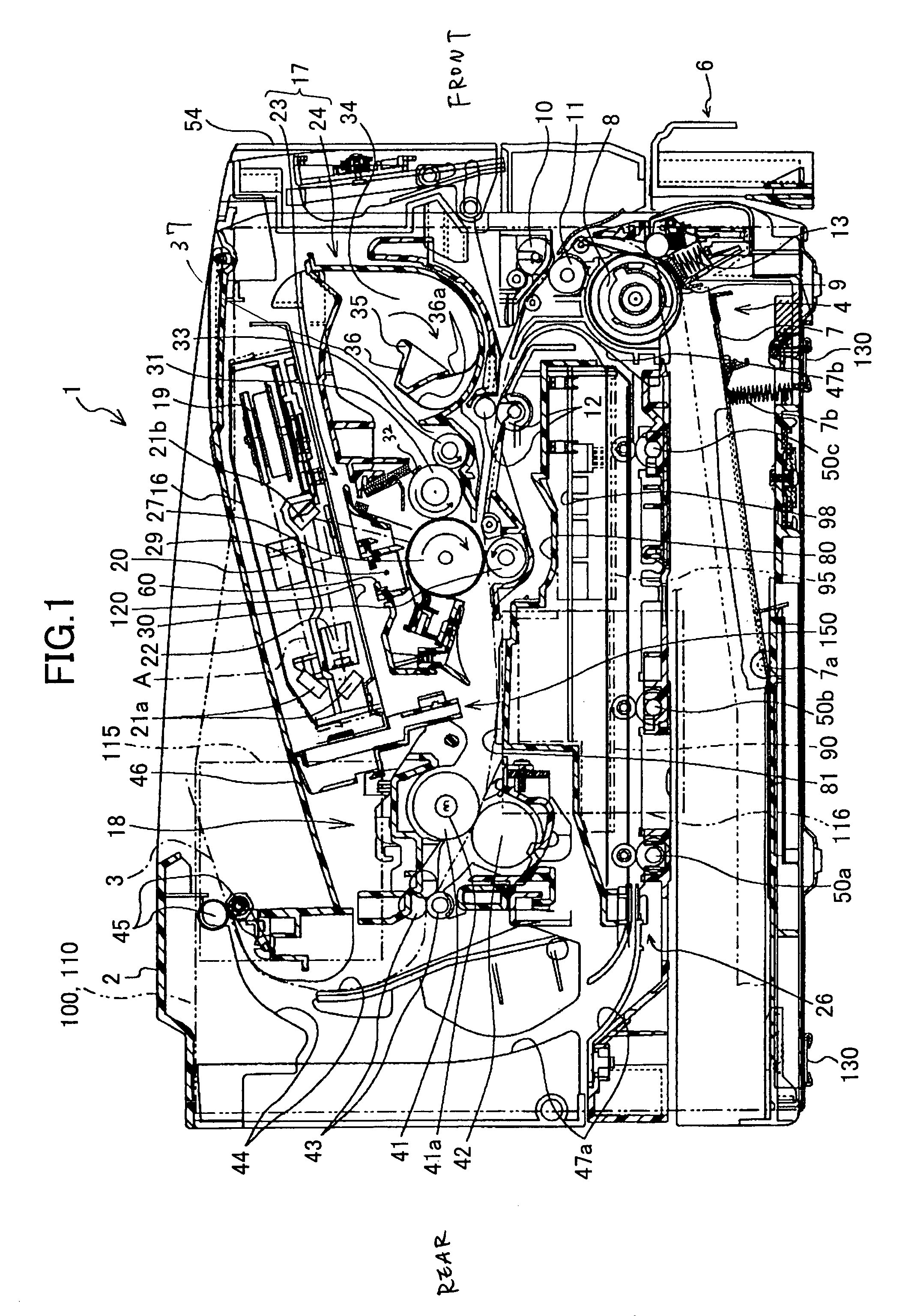
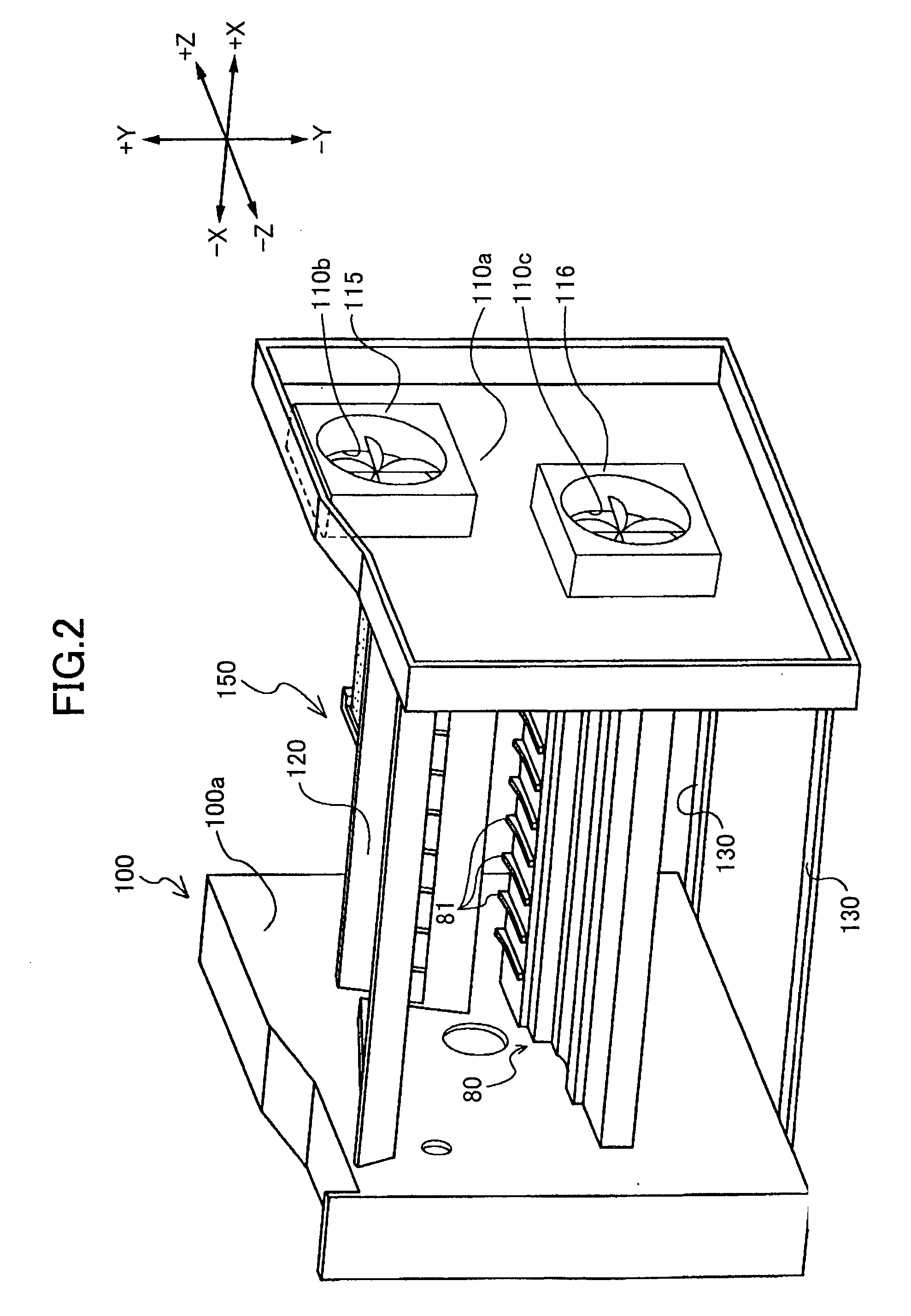
[0022] A laser printer 1 according to an embodiment of the present invention will be described with reference to the accompanying drawings. It should be noted that, in FIGS. 2 to 6, directions -Z, -X, +X, +Z, +Y, and -Y indicate frontward, leftward, rightward, rearward, upward, and downward directions, respectively, of the laser printer 1. First, overall structure of the laser printer 1 will be described with reference to FIG. 1.

[0023] As shown in FIG. 1, the laser printer 1 includes a feeder section 4, an image forming section, and a duplex printing unit 26, all accommodated in a main body case 2. The feeder section 4 is for feeding a sheet 3. The image forming section is for forming a predetermined image on the fed sheet 3, and includes a scanner unit 16, a process cartridge 17, and a fixing unit 18.

[0024] The process cartridge 17 is housed in a space provided close to the front upper surface of the main body case 2. The space is covered by a cover 54, which is provided on the fro...


PUM


Abstract

A low-voltage power source circuit board is provided downstream in relation to the flow of air introduced through an intake hole and exhausted by a power source fan. Heat sinks are provided on the low-voltage power source circuit board on electronic parts that generate a large amount of heat, the plate surfaces of the heat sinks being arranged along the direction of airflow, thereby minimizing their resistance to the airflow. Air including heat generated from these electronic parts is exhausted by the power source fan without the air heating the high-voltage power source circuit board or engine circuit board that are disposed upstream in relation to the direction of airflow.

Description

[0001] 1. Field of the Invention[0002] The present invention relates to an image forming device capable of exhausting air that contains heat generated by a power source circuit board from a main casing of the image forming device so as not to affect other circuit boards.[0003] 2. Description of the Related Art[0004] Conventional image forming devices, such as laser printers and copy machines, have a photosensitive member with a charge generating layer and a charge transporting layer formed over a base layer. A charge is applied to the photosensitive member by performing a corona discharge, and the charged photosensitive member is exposed to light, such as laser light or LED light, to form an electrostatic latent image. After the latent image is developed with toner or another developer, the developed image is transferred onto a recording medium. The image formation is completed when the image is fixed onto the recording medium by applying heat from a fixing unit or the like. Heat th...

Claims


Application Information

Patent Timeline
Patent Type & Authority Applications(United States)
IPC IPC(8): G03G15/20G03G21/00G03G21/16G03G21/20H05K7/20
CPCH05K7/20145G03G15/80G03G15/2039
Inventor YOSHIHARA, HIDEOUKAI, MASAMITSUHATTORI, YOSHITERU
Owner BROTHER KOGYO KK
Learn More