
Method for asymptotic dipping correction

a correction method and asymptotic technology, applied in the field of correction methods for induction well logging measurements, can solve problems such as errors introduced into the tool response, tool error is commonly known as the "nonlinear shoulder effect", and assume failur

Inactive Publication Date: 2004-05-06
HALLIBURTON ENERGY SERVICES INC
View PDF1 Cites 18 Cited by
  • Summary
  • Abstract
  • Description
  • Claims
  • Application Information

AI Technical Summary

Benefits of technology

0024] Another method determines shoulder effect error based on modeling tool response at a depth-of-interest without dip and modeling tool response with the elimi

Problems solved by technology

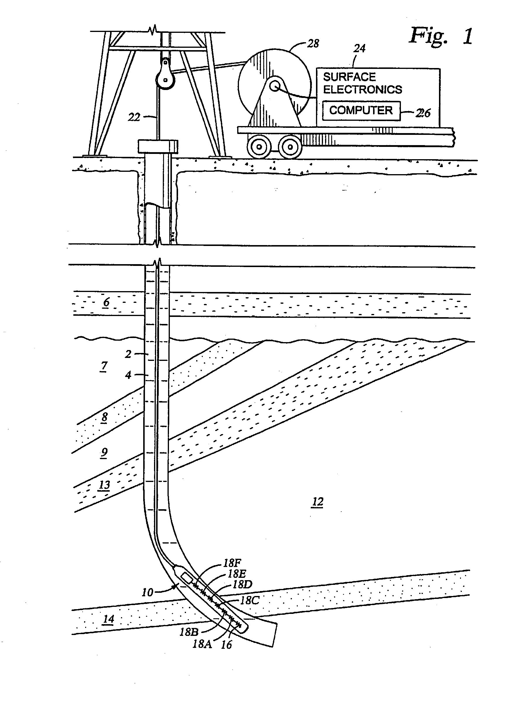
This assumption fails in cases where layers of the earth formations are not perpendicular to, but are inclined with respect to, the axis of the wellbore (and consequently the axis of the instrument).
When the ground loops cross one or more bed boundaries, errors are introduced into the tool response.
Another tool error is commonly known as the "nonlinear shoulder effect."
While the induction tool is proximate these bed boundaries, a portion of the receiver response comes from the bed or beds adjacent the bed in which the tool lies, introducing error into the measurements.
It has been established that a portion of this tool response error in the regions proximate bed boundaries is non-linear.
This nonlinearity makes it difficult to evaluate exactly the response portion that is from the adjacent bed, leading to an incorrect evaluation of the conductivity of the bed of interest.
Thus, an induction tool at an angle to a formation bed produces a series of inaccurate measurements.
Of course, if not corrected for, the dipping error and shoulder bed error made in the raw measurements are reflected by inaccuracies in the formation resistivity well logs.
However, much of the discussion is centered around solutions that are inaccurate, or slow, or complicated.
Most of the methods in the literature that attempt to correct for at least a portion of the dipping error and shoulder bed effect error are incompatible with, or at least unduly complicate, these previous resistivity log interpretation techniques.

Method used


Image

  • Method for asymptotic dipping correction
  • Method for asymptotic dipping correction
  • Method for asymptotic dipping correction

Examples


Embodiment Construction

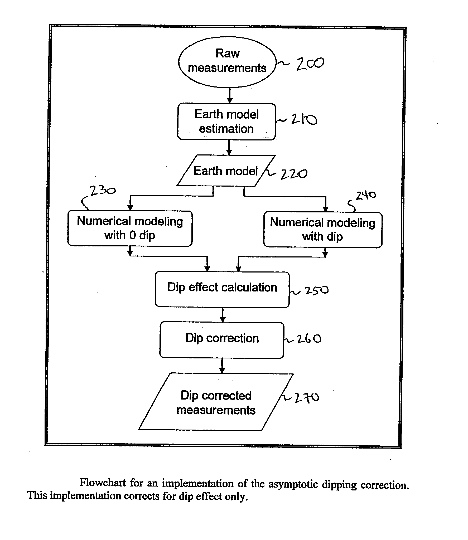
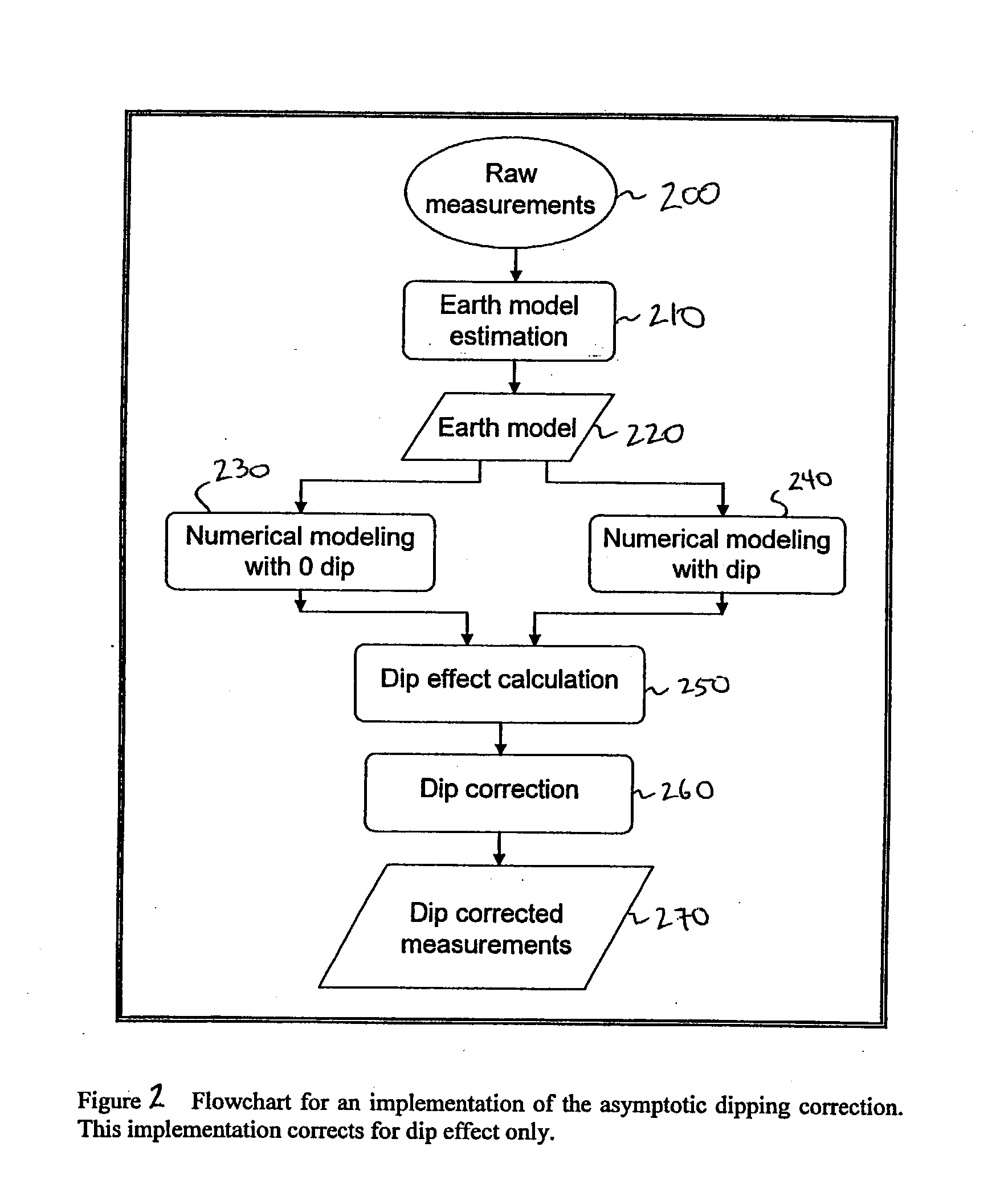
[0023] The problems noted above are solved in large part by a method that determines dip error based on modeling or describing tool response at a depth-of-interest both with and without dip. The difference between the two modeled responses is defined as the dip error.

[0024] Another method determines shoulder effect error based on modeling tool response at a depth-of-interest without dip and modeling tool response with the elimination of the linear component of the shoulder bed effect. The difference between the two modeled responses is the non-linear component of the shoulder bed effect.

[0025] These methods may also be integrated into a system including a induction logging tool and a processor.

[0026] The disclosed devices and methods comprise a combination of features and advantages which enable it to overcome the deficiencies of the prior art devices. The various characteristics described above, as well as other features, will be readily apparent to those skilled in the art upon re...


PUM


Abstract

Induction and other resistivity well logging tools determine formation conductivity at various depths but these measurements contain pronounced errors when the tool is proximate to an inclined underground bed boundary. A method to correct tool measurements includes calculating an expected tool response at a relative dip angle of zero degree and at a particular depth based on an earth model of the underground formation. An expected tool response at the known dip is then calculated. Comparing the calculated zero-dip response with the calculated non-zero-dip response yields the dip effect. A response is also modeled to exclude the non-linearity of the shoulder effect. Comparing the calculated linear response (obtained, e.g. by the Born approximation) with the calculated zero-dip response yields the nonlinear shoulder effect. The nonlinear shoulder effect and / or the dip effect may then be corrected for by subtracting them from the raw or pre-processed measurements.

Description

[0001] Not applicable.[0002] Not applicable.[0003] 1. Field of the Invention[0004] The present invention is directed to induction well logging. More particularly, the invention relates to a correction method for induction well logging measurements.[0005] 2. Background of the Invention[0006] Modern petroleum drilling and production operations demand a great quantity of information relating to parameters and conditions downhole. Such information typically includes characteristics of the earth formations traversed by the wellbore, in addition to data relating to the size and configuration of the borehole itself. The collection of information relating to conditions downhole, which commonly is referred to as "logging," can be performed by several methods. Oil well logging has been known in the industry for many years as a technique for providing information to a driller regarding the particular earth formation being drilled. In conventional oil well wireline logging, a probe or "sonde" i...

Claims


Application Information

Patent Timeline
IPC IPC(8): G01V3/28
CPCG01V3/28
Inventor XIAO, JIAQI
Owner HALLIBURTON ENERGY SERVICES INC
Learn More