Medical valve and method of use

a technology of medical valves and valve bodies, applied in the field of closed patient access systems, can solve the problems of introducing air embolisms into patients, affecting the safety of patients,

Inactive Publication Date: 2004-04-15
LOPEZ GEORGE A
View PDF99 Cites 38 Cited by
  • Summary
  • Abstract
  • Description
  • Claims
  • Application Information

AI Technical Summary

Benefits of technology

[0011] This invention is a closed, patient access system which automatically reseals after administering medication using a medical implement that directly connects with the system without the need of any intermediate needles, caps or adaptors. A two-way valve is employed utilizing a reusable seal that may be repeatedly pierced by an enclosed, protected, non-metallic spike rather than an exposed metal needle. The valve facilitates fluid, particularly liquid, transfer while maintaining sterility. The valve is easy to use and is capable of locking in place. After use, the valve is swabbed in the conventional manner with a suitable substance to maintain sterility. The design of the valve avoids accidental needle sticks. As will be discussed in detail below, the valve is useful as a medical connector or adaptor to enable liquid flow from a sealed container.
[0017] The fifth feature is that the medical valve includes a support member connected to the spike which seals off the distal end of the cavity. The support member may have a Luer-Lock type connector element that enables the valve to be removably attached to, for example, a fluid line connected to a patient. The support member may also be in the form of an adaptor that enables the valve to be removably attached to a fluid dispenser or container. When used to dispense fluids from a container, the spike has a pair of opposed tips, respectively at the distal and proximal ends of the spike. The tip at the distal end of the spike pierces a cover member which seals the container. A radial slit on the adaptor enables it to deform reversibly sufficiently to fit snugly onto said container.
[0018] The sixth feature is that the seal has a proximal end including a pressure responsive element disposed on an inner surface of the seal adjacent the opening. The pressure responsive element in the decompressed state closes any orifice in the seal at the proximal end of the seal to provide an essentially fluid-tight seal while in the decompressed state. The pressure responsive element enables the valve to maintain a fluid-tight seal even at very high pressures sometimes experienced in medical applications, particularly when the valve is connected to a patient's artery. The valve of this invention will remain closed even when the pressure inside the valve is above 6 pounds per square inch (psi), and it can withstand pressures above 30 psi. Typically, the pressure responsive element is a section of the seal having an entryway into a precut orifice. This section has a substantially cylindrical configuration and is surrounded by an annular space which is filled with pressurized fluid. The center of the member and the annular space are coaxial with the entryway to the orifice. The pressurized fluid fills the annular space to apply pressure that compresses the cylindrical section to tightly close the entryway to the orifice. Preferably, the pressure responsive element has an anti-tear element.

Problems solved by technology

Adaptors and connectors that malfunction during use may be life-threatening.
The more mechanical or moving parts such as springs and diaphragms, the more likely that they will function improperly.
Improper functioning can result in the introduction of air embolisms into a patient.
This "dead space" within the device prevents accurate introduction of precise fluid volumes and provides an opportunity for contamination upon disconnection of the device.
These connectors often require further manipulation if, for example, the valve is inadvertently assembled in a direction that will not facilitate fluid flow.
These manipulations increase handling, thereby increasing both the risk of contamination and the amount of time required to establish the fluid connection.
Metal needles employed as part of connector devices increase the risk of puncture wounds to the user.
Such an event can prove fatal to a patient.
Such through-holes may also become clogged easily with material from the septum.
Reusable connectors, however, are difficult to keep sterile.
Frequently, these caps are lost, or simply not used because they are not readily available when needed.
Rough edges at the tip may present a tear problem.

Method used


Image

  • Medical valve and method of use
  • Medical valve and method of use
  • Medical valve and method of use

Examples


Embodiment Construction

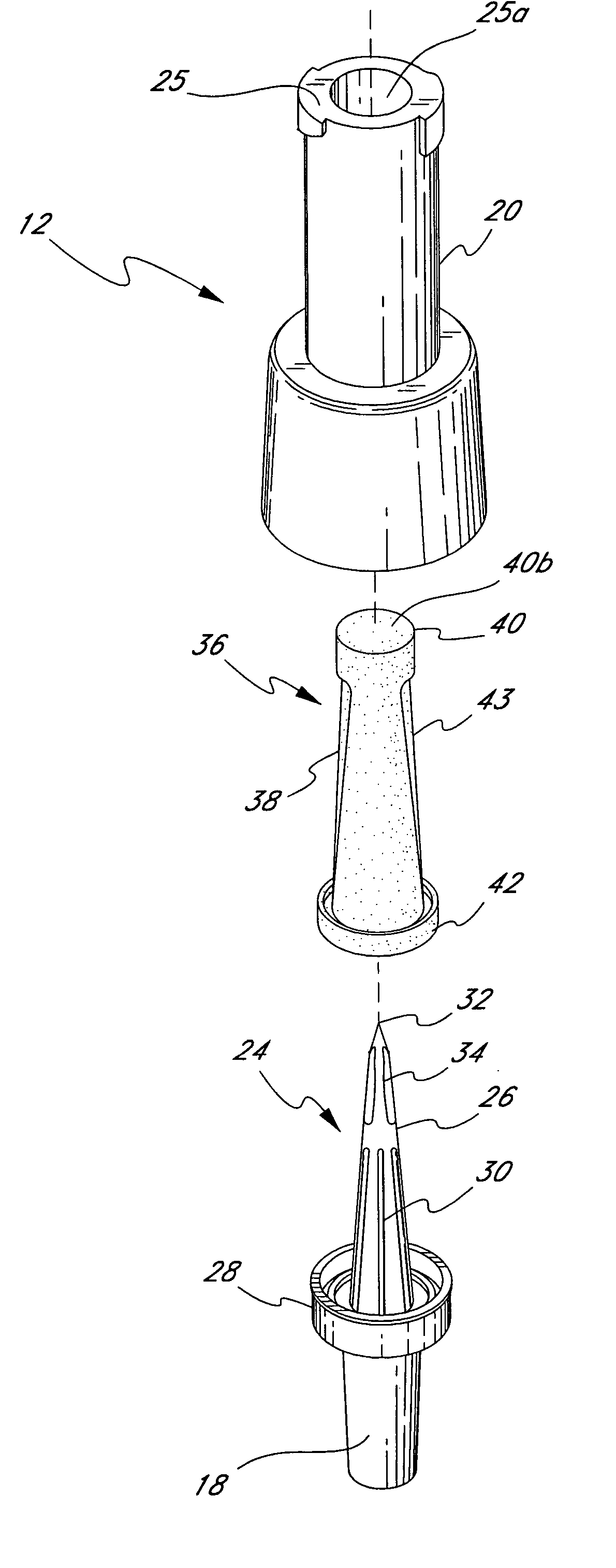
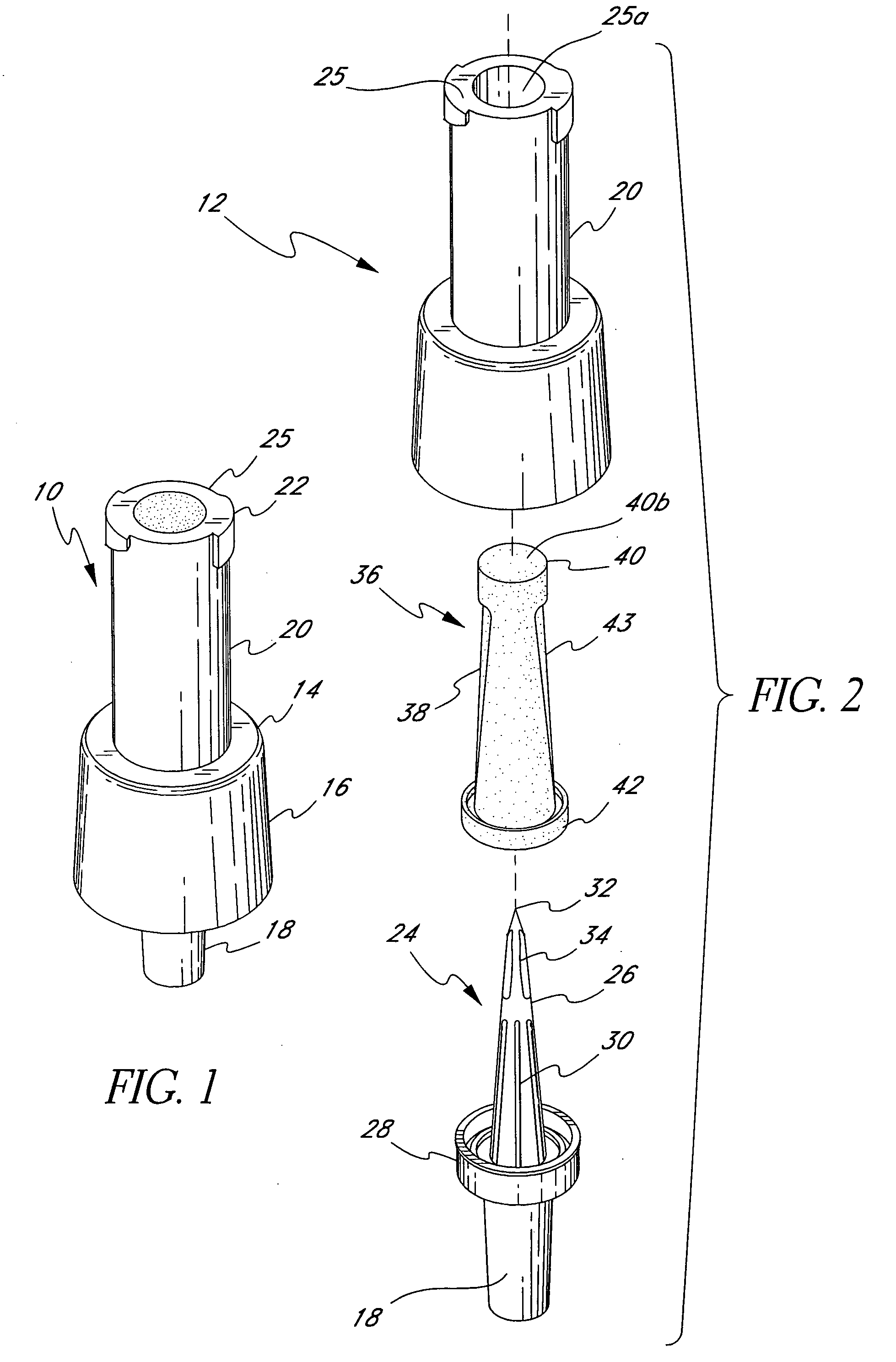
[0043] The term "proximal" is used to denote the end of the valve and other components at or near the spike tip 32 in FIGS. 2 through 5, 10 through 12, 14 and 16, and at or near the spike tip 60 in FIG. 6, and at or near the seal cap 92 in FIGS. 8, 9, 13 through 19. The term "distal" is used to denote the opposite end of the valve, or spike tip, or seal. The term "medical implement" is used to denote any medical tool known to those of skill in the art that can connect to the present invention and facilitate the passage of fluids, particularly liquids, through the instant invention. Examples of medical implements that are contemplated include, but are not limited to, tubing, conduit, syringes, IV sets (both peripheral and central lines), piggyback lines, and other components which can be used in connection with medical valve. Medical implements are commercially available in standard sized. Thus, either or both ends of the valve of this invention can be provided with fittings to accom...


PUM


Abstract

A closed system, needleless valve device includes a generally tubular body defining an internal cavity. On the proximal end of the body there is an opening which is preferably sufficiently large to receive an ANSI standard tip of a medical implement. The distal end of the body has a generally tubular skirt. The valve also includes a hollow spike having a closed tip. The spike includes at least one longitudinal 18-gauge hole located distal the tip, and is seated inside the cavity such that the tip is below the proximal end of the body. An annular support cuff is connected to the spike which seals off a portion of the cavity of the body such that an upper cavity containing the tip is defined. The valve also includes a plastic, resilient silicone seal which fills the upper cavity and opening and covers the tip of the spike so as to present a flush surface. An adaptor enables the valve to be attached to a resealable container.

Description

[0001] This application is a continuation of U.S. application Ser. No. 10 / 163,403, filed Jun. 5, 2002, which was a continuation of U.S. application Ser. No. 09 / 569,712, filed May 9, 2000, now U.S. Pat. No. 6,572,592, which was a continuation of U.S. application Ser. No. 08 / 905,370, filed Aug. 4, 1997, now abandoned, which was a continuation of U.S. application Ser. No. 08 / 334,846, filed Nov. 4, 1994, now U.S. Pat. No. 5,685,866, which was a continuation of U.S. application Ser. No. 08 / 096,659, filed Jul. 23, 1993, now U.S. Pat. No. 5,695,466, which was a continuation-in-part of PCT Application No. PCT / US92 / 10367, filed Dec. 1, 1992, now abandoned, which was continuation-in-part of U.S. application Ser. No. 07 / 813,073, filed Dec. 18, 1991, now abandoned.[0002] 1. Field of the Invention[0003] This invention relates to a closed, patient access system which automatically reseals after administering medication using a standard medical implement that directly connects with the system with...

Claims


Application Information

Patent Timeline
Patent Type & Authority Applications(United States)
IPC IPC(8): A61M5/14A61M5/168A61M5/162A61M25/16A61M39/00A61M39/04A61M39/14A61M39/22A61M39/26F16K27/00F21K2/00
CPCA61J2200/10A61M5/14A61M39/045A61M39/26Y10S604/905A61M2205/32A61M2205/583A61M2205/6063F21K2/00A61M2039/262A61M2039/267
Inventor LOPEZ, GEORGE A.
Owner LOPEZ GEORGE A
Why Eureka
Try Eureka