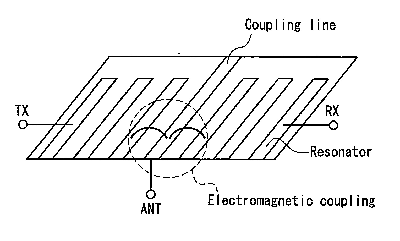
Duplexer, and laminate-type high-frequency device and communication equipment using the same
a high-frequency device and laminate-type technology, applied in coupling devices, electrical devices, waveguides, etc., can solve the problems of reducing the degree of design freedom, increasing the loss of branching circuits, and increasing the layout spa
- Summary
- Abstract
- Description
- Claims
- Application Information
AI Technical Summary
Problems solved by technology
Method used
Image
Examples
embodiment 1
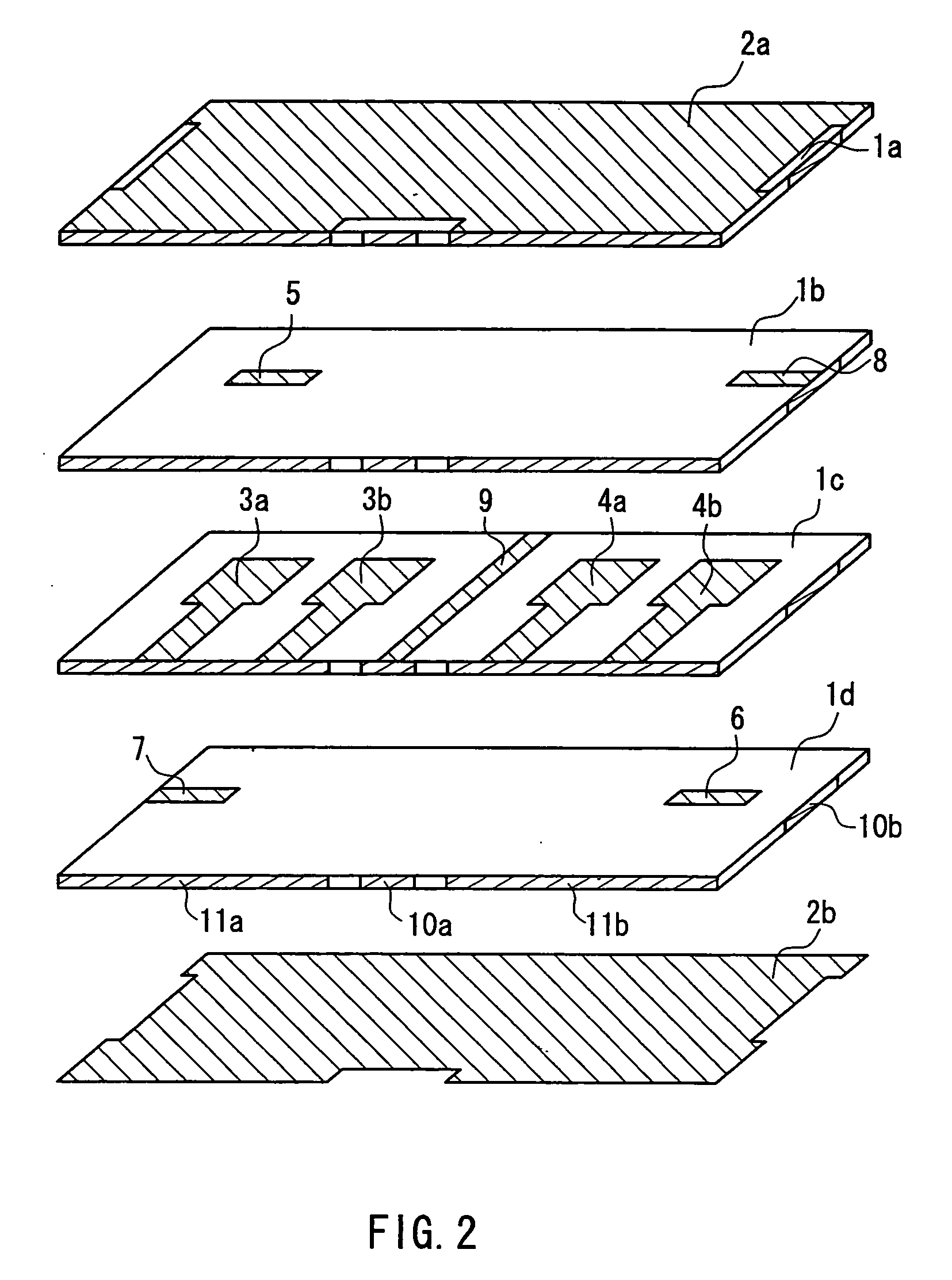
[0092] FIG. 2 is an exploded perspective view showing a duplexer of the present invention.
[0093] As shown in FIG. 2, the duplexer according to the present embodiment is composed of a laminate in which dielectric layers and electrode layers are laminated alternately. In the laminate, a first filter for transmitting and a second filter for receiving, having different pass band frequencies, are provided. Furthermore, a matching circuit composed of a coupling line 9, having one end that is short-circuited and the other end that is connected to an external terminal, is provided between the first filter and the second filter.
[0094] The first filter includes two first stripline resonators 3a and 3b, each having one end that is short-circuited. The second filter includes two second stripline resonators 4a and 4b, each having one end that is short-circuited. The coupling line 9 is coupled to the first stripline resonator 3b close to the coupling line 9 by electromagnetic field coupling. The...
embodiment 2
[0106] FIG. 6 is an exploded perspective view showing a duplexer according to Embodiment 2 of the present invention. The duplexer according to the present embodiment is the same as that according to Embodiment 1 except for the points described below. Therefore, like components are denoted with like numerals, and their description will be omitted here.
[0107] As shown in FIG. 6, in the duplexer according to the present embodiment, the first stripline resonators 3a, 3b and the second stripline resonators 4a, 4b are formed on dielectric layers 1c, 1e, different from the dielectric layer 1d on which the coupling line 9 is formed. Thus, by forming the first stripline resonators 3a, 3b and the second stripline resonators 4a, 4b on the dielectric layers 1c, 1e different from the dielectric layer 1d on which the coupling line 9 is formed, the degree of design freedom and versatility can be provided.
[0108] Furthermore, the coupling line 9 is composed of two striplines (wide portion and narrow...
embodiment 3
[0111] FIG. 7 is an exploded perspective view showing a duplexer according to Embodiment 3 of the present invention. The duplexer according to the present embodiment is the same as that according to Embodiment 2 except for the points described below. Therefore, like components are denoted with like numerals, and their description will be omitted here.
[0112] As shown in FIG. 7, in the duplexer according to the present embodiment, the coupling line is composed of three striplines 9a, 9b, and 9c, and the three striplines 9a, 9b, and 9c are provided on different dielectric layers 1c, 1d, and 1e, respectively. In the case where there is only one stripline, an electric potential is fluctuated. However, by using three striplines, the electric potential can be stabilized.
[0113] It is desirable that at least one of the three striplines 9a, 9b, and 9c has a line width different from those of the others. In the present embodiment, all the striplines 9a, 9b, and 9c are configured so as to have ...
PUM
 Abstract
Description
Claims
Application Information
 - R&D
- Intellectual Property
- Life Sciences
- Materials
- Tech Scout
- Unparalleled Data Quality
- Higher Quality Content
- 60% Fewer Hallucinations
Browse by: Latest US Patents, China's latest patents, Technical Efficacy Thesaurus, Application Domain, Technology Topic, Popular Technical Reports.
© 2025 PatSnap. All rights reserved.Legal|Privacy policy|Modern Slavery Act Transparency Statement|Sitemap|About US| Contact US: help@patsnap.com


