
Ruggedized multi-layer printed circuit board based downhole antenna

a printed circuit board and antenna technology, applied in the field of downhole tools, can solve the problems of neither device is capable of performing azimuthally sensitive resistivity measurements in oil-based drilling fluids, and the tool shown in fig. 1 is not suited for azimuthally sensitive readings

Inactive Publication Date: 2004-03-25
HALLIBURTON ENERGY SERVICES INC
View PDF6 Cites 29 Cited by
  • Summary
  • Abstract
  • Description
  • Claims
  • Application Information

AI Technical Summary

Benefits of technology

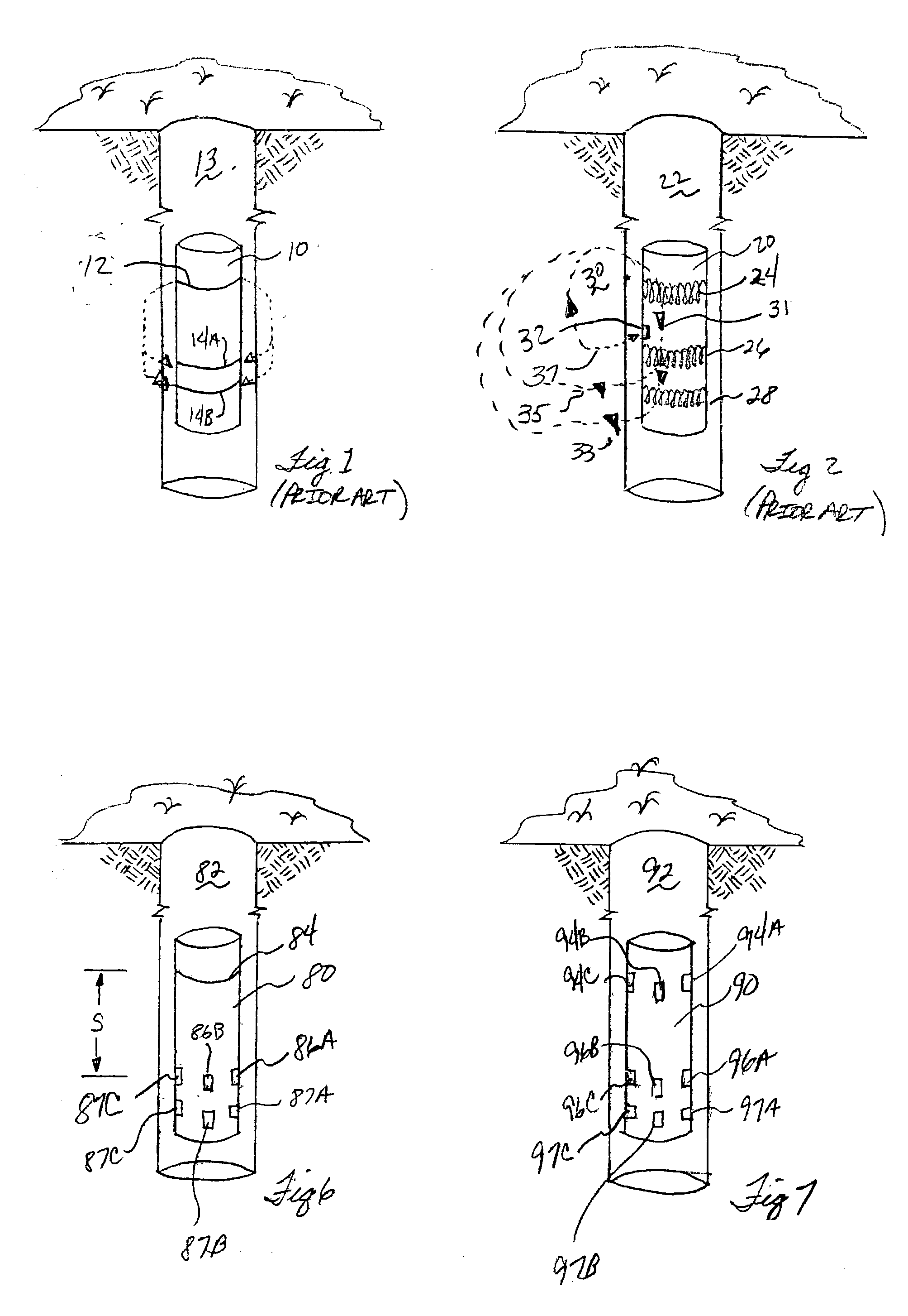
[0012] More particularly, the ruggedized PCB based ferrite core antenna may be utilized on a downhole tool to make azimuthally sensitive resistivity measurements, and may also be used to make resistivity based borehole wall images. In a first embodiment, a tool comprises a loop antenna at a first elevation used as an electromagnetic source. At a spaced apart location from the loop antenna a plurality of PCB based ferrite core antennas are coupled to the tool along its circumference. The loop antenna generates an electromagnetic signal that is detected by each of the plurality of PCB based ferrite core antennas. The electromagnetic signal received by the PCB based ferrite core antennas are each in azimuthally sensitive directions, with directionality dictated to some extent by physical placement of the antenna on the tool. If the spacing between the loop antenna and the plurality of PCB based antennas is relatively short (on the order of six inches), then the tool may perform borehole imaging. Using larger spacing between the loop antenna and the plurality of PCB based ferrite core antennas, and a second plurality of PCB based ferrite core antennas, azimuthally sensitive electromagnetic wave resistivity measurements of the surrounding formation are possible.

Problems solved by technology

Thus, tools such as that shown in FIG. 1 are not suited for taking azimuthally sensitive readings, such as for borehole imaging.
However, wave propagation tools such as that shown in FIG. 1, which operate using electromagnetic radiation or electromagnetic wave propagation (an exemplary path of the wave propagation shown in dashed lines) are capable of operation in a borehole utilizing oil-based (non-conductive) drilling fluid, a feat not achievable by conduction-type tools.
While each of the wave propagation tool of FIG. 1 and conduction tool of FIG. 2 has its uses in particular circumstances, neither device is capable of performing azimuthally sensitive resistivity measurements in oil-based drilling fluids.

Method used


Image

  • Ruggedized multi-layer printed circuit board based downhole antenna
  • Ruggedized multi-layer printed circuit board based downhole antenna
  • Ruggedized multi-layer printed circuit board based downhole antenna

Examples


first embodiment

[0012] More particularly, the ruggedized PCB based ferrite core antenna may be utilized on a downhole tool to make azimuthally sensitive resistivity measurements, and may also be used to make resistivity based borehole wall images. In a first embodiment, a tool comprises a loop antenna at a first elevation used as an electromagnetic source. At a spaced apart location from the loop antenna a plurality of PCB based ferrite core antennas are coupled to the tool along its circumference. The loop antenna generates an electromagnetic signal that is detected by each of the plurality of PCB based ferrite core antennas. The electromagnetic signal received by the PCB based ferrite core antennas are each in azimuthally sensitive directions, with directionality dictated to some extent by physical placement of the antenna on the tool. If the spacing between the loop antenna and the plurality of PCB based antennas is relatively short (on the order of six inches), then the tool may perform borehol...

second embodiment

[0013] In a second embodiment, a first plurality of PCB based ferrite core antennas are spaced around the circumference of a tool at a first elevation and used as an electromagnetic source. A second and third plurality of PCB based ferrite core antennas are spaced about the circumference of the tool at a second and third elevation respectively. The first plurality of PCB based antennas may be used sequentially, or simultaneously, to generate electromagnetic signals propagating to and through the formation. The electromagnetic waves may be received by each of the second and third plurality of PCB based antennas, again allowing azimuthally sensitive resistivity determinations.

[0014] Because the PCB based ferrite core antennas of the preferred embodiment are capable of receiving electromagnetic wave propagation in an azimuthally sensitive manner, and because these antennas are operational on the philosophy of an induction-type tool, it is possible to utilize the antennas to make azimut...


PUM


Abstract

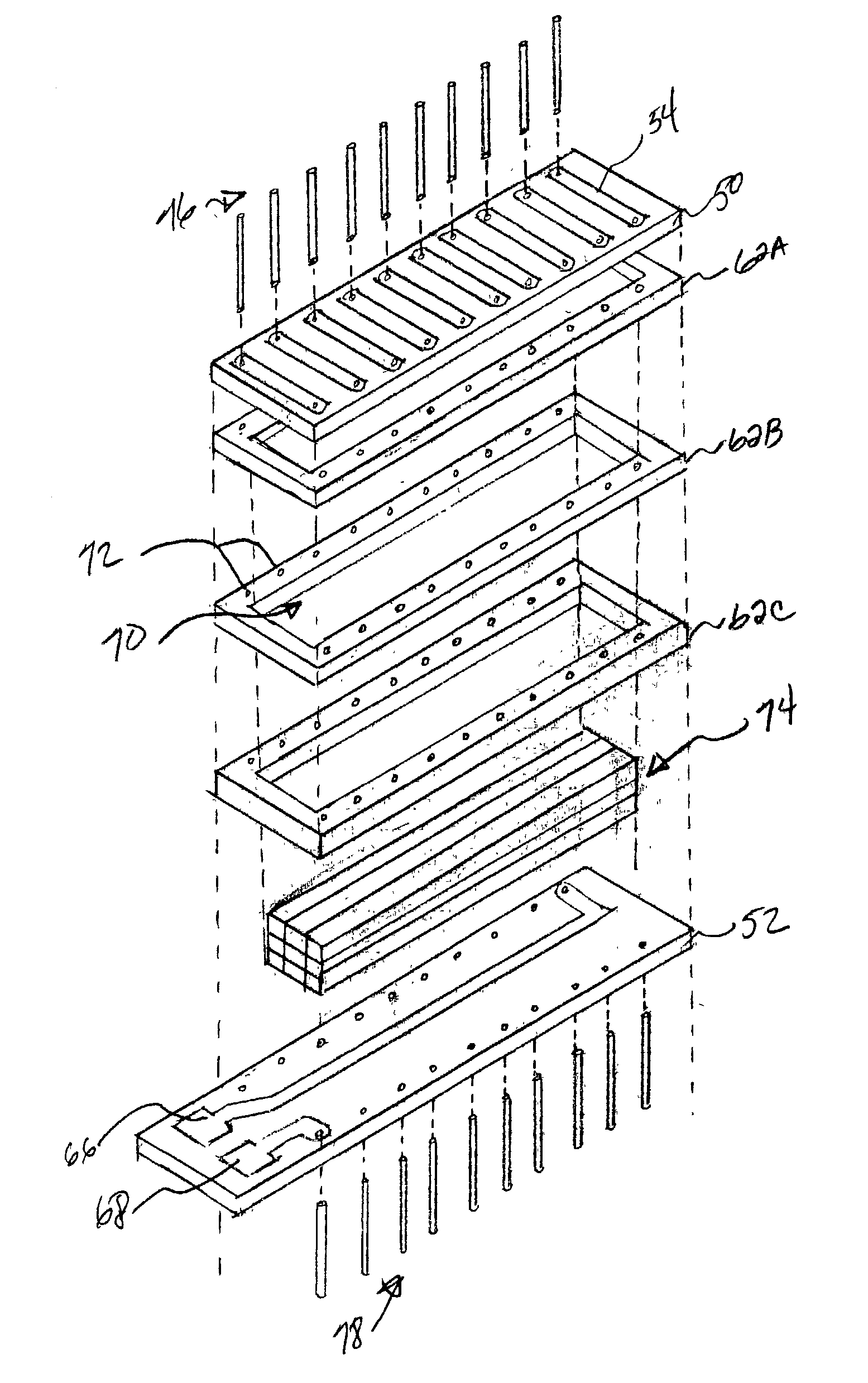
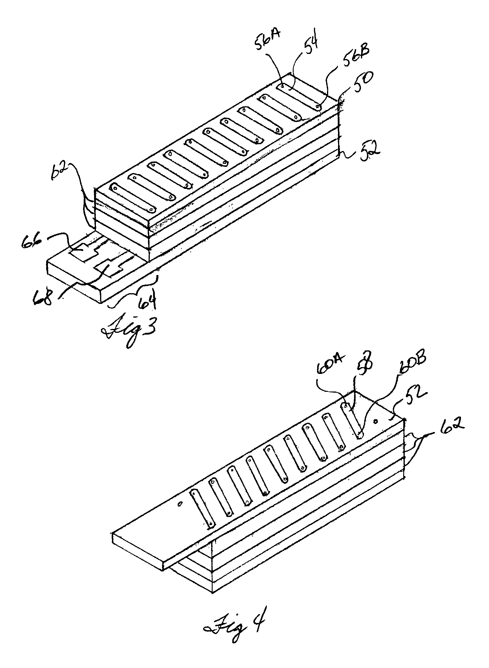
The specification discloses a printed circuit board (PCB) based ferrite core antenna. The traces of PCBs form the windings for the antenna, and various layers of the PCB hold a ferrite core for the windings in place. The specification further discloses use of such PCB based ferrite core antennas in downhole electromagnetic wave resistivity tools such that azimuthally sensitivity resistivity readings may be taken, and borehole imaging can be performed, even in oil-based drilling fluids.

Description

[0001] None.[0002] Not applicable.[0003] 1. Field of the Invention[0004] The preferred embodiments of the present invention are directed generally to downhole tools. More particularly, the preferred embodiments are directed to antennas that allow azimuthally sensitive electromagnetic wave resistivity measurements of formations surrounding a borehole, and for resistivity-based borehole imaging.[0005] 2. Background of the Invention[0006] FIG. 1 exemplifies a related art induction-type logging tool. In particular, the tool 10 is within a borehole 13, either as a wireline device or as part of a bottomhole assembly in a measuring-while-drilling (MWD) process. Induction logging-while-drilling (LWD) tools of the related art typically comprise a transmitting antenna loop 12, which comprises a single loop extending around the circumference of the tool 10, and two or more receiving antennas 14A and 14B. The receiving antennas 14A, B are generally spaced apart from each other and from the tran...

Claims


Application Information

Patent Timeline
IPC IPC(8): H01Q1/04H01Q1/38H01Q7/08
CPCH01Q1/04H01Q7/08H01Q1/38G01V3/30
Inventor BITTAR, MICHAEL S.HENSARLING, JESSE K.
Owner HALLIBURTON ENERGY SERVICES INC
Learn More