
Particulate blaster assembly and aspirator

a blaster and particulate technology, applied in the field of sandblasters, can solve the problems of long deferred maintenance of graffiti removal, large volume of conventional sandblasters, and large equipment dedicated to sandblasting, and achieve the effect of enhancing cooperative pressur

Inactive Publication Date: 2004-03-04
DANIEL DORCE L
View PDF14 Cites 8 Cited by
  • Summary
  • Abstract
  • Description
  • Claims
  • Application Information

AI Technical Summary

Benefits of technology

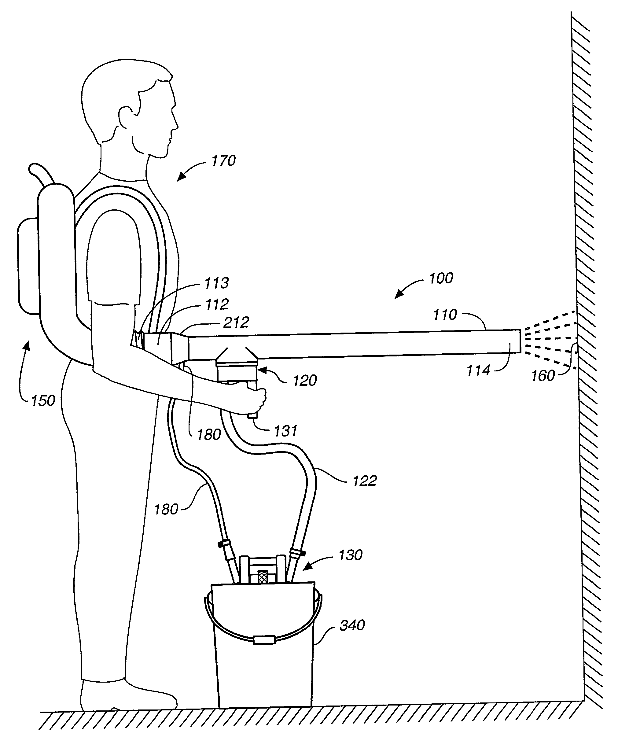
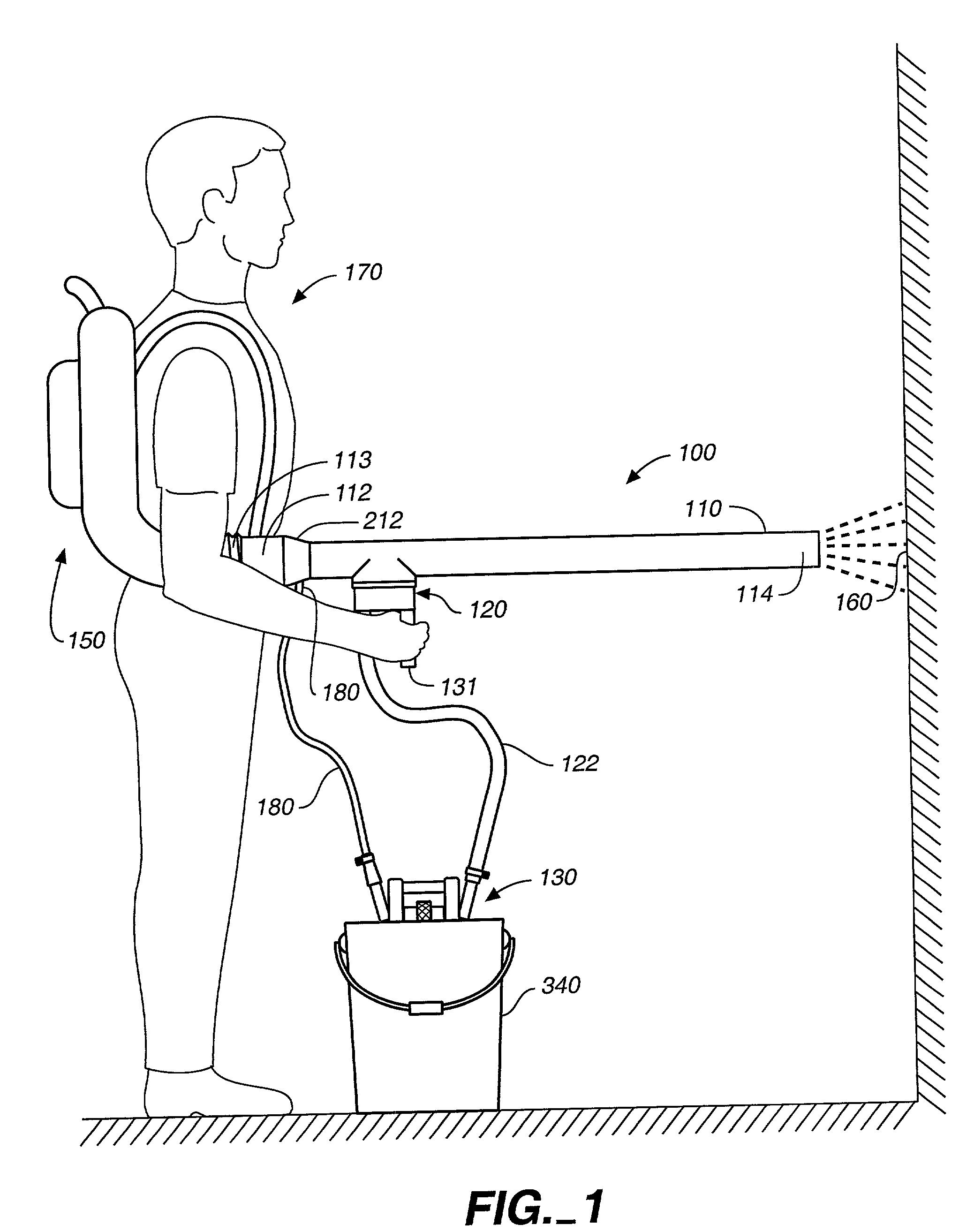
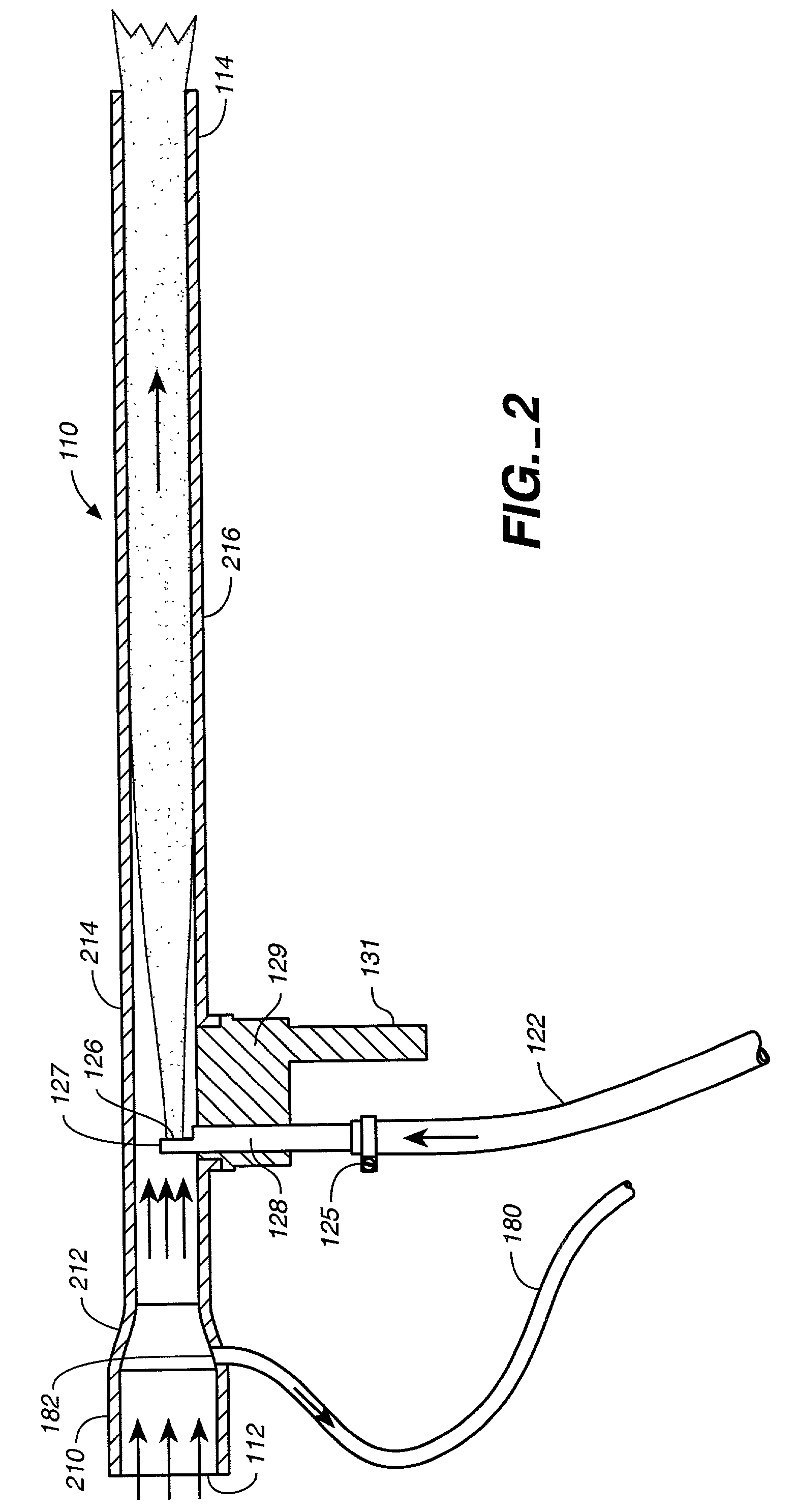
[0008] Another aspect of the present invention is directed to a particulate material aspirator assembly for the blaster which is responsive to a vacuum source to aspirate particulate material from a particulate material source, usually a portable source such as a bucket filled with sand. The aspirator assembly includes a base gravity support on a top surface of the sand in the container. A vacuum conduit, passing through the base, extends below the base and has an open vacuum end for aspirating the particulate material from the container. An opposite end of the vacuum conduit is coupled to the vacuum generating structure. Most preferably, the aspirator assembly also includes a pressure conduit mounted to the base and having an inlet end coupled to a source of pressure and an open pressure end extending below the base to a position proximate the open vacuum of the vacuum conduit. The vacuum conduit and the pressure conduit may be movably mounted to the base to vary the distance between the open vacuum end and the open pressure end so as to enhance the cooperative pressure and vacuum in fluidizing the particulate material and entraining it in the air being communicated to the air directing tube. The open vacuum end and the open pressure end preferably extend below the base by a vertical distance greater than the height of the angle of repose of the particulate material.

Problems solved by technology

Thus, the rapidly moving sand will hit the target site with considerable force and thereby remove surface material, for example, mold, rust, paint, and similar abradable substances.
Unfortunately, conventional sandblasters are usually quite massive and require bulky air compressors and expensive equipment dedicated specifically to sandblasting.
Such sandblasting equipment is expensive to own or lease, and as a result, graffiti removal is often a long deferred maintenance problem.

Method used


Image

  • Particulate blaster assembly and aspirator
  • Particulate blaster assembly and aspirator
  • Particulate blaster assembly and aspirator

Examples


Embodiment Construction

[0014] Reference will now be made in detail to the preferred embodiments of the invention, examples of which are illustrated in the accompanying drawings. While the invention will be described in conjunction with the preferred embodiments, it will be understood that they are not intended to limit the invention to those embodiments. On the contrary, the invention is intended to cover alternatives, modifications and equivalents, which may be included within the spirit and scope of the invention as defined by the appended claims.

[0015] Turning now to the drawings, wherein like components are designated by like reference numerals throughout the various figures, attention is directed to FIG. 1, where a particulate blaster assembly, generally designated 100, is illustrated. Particulate blaster assembly 100 includes an air directing tube 110, a vacuum generating assembly, generally designated 120, and a particulate material aspirator, generally designated 130. The air directing tube includ...


PUM


Abstract

A particulate blaster assembly (100) for use as an attachment to a portable air blower (150) includes an air directing tube (110), a vacuum generating assembly (120), and a particulate material aspirator (130). The air directing tube (110) has an inlet end (112) formed for coupling to the air blower (150) to receive air discharged therefrom and a movable exhaust end (114) formed for discharge of air and particulate material (212) entrained in the air toward a target site (160). The vacuum assembly (120) is coupled to the air directing tube (110) and formed to produce a partial vacuum as air passes in the tube (110) over the vacuum generating assembly (120). The particulate material aspirator (130) is coupled to the vacuum assembly (120) and is responsive to the partial vacuum generated by the vacuum generating assembly (120) to aspirate a particulate material (212) from a particulate material source (340) into the air directing tube (110) for acceleration and discharge of the entrained particulate material (212). Preferably, a positive pressure, generating assembly (182) communicates positive pressure to aspirator (130) for cooperation with the partial vacuum at the aspirator (130) to aspirate particulate material (212) into the air directing tube (110).

Description

[0001] 1. Field of the Invention[0002] This invention relates, in general, to sandblasters, and more particularly, relates to highly portable particulate blaster devices.[0003] 2. Description of Related Art[0004] Sandblasters entrain a hard particulate material, typically fine sand, in a stream of air which can be directed against a target site to be ablated or abrasively eroded by the sand. Thus, the rapidly moving sand will hit the target site with considerable force and thereby remove surface material, for example, mold, rust, paint, and similar abradable substances. Unfortunately, conventional sandblasters are usually quite massive and require bulky air compressors and expensive equipment dedicated specifically to sandblasting.[0005] One wide spread use of sandblasting equipment is the removal of graffiti, particularly from concrete structures. Private property owners and municipalities have a substantial continuing graffiti problem and it is often periodically addressed by sand...

Claims


Application Information

Patent Timeline
Patent Type & Authority Applications(United States)
IPC IPC(8): B24C5/02
CPCB24C5/02
Inventor DANIEL, DORCE L.
Owner DANIEL DORCE L
Learn More