
Magnetic sensor unit less responsive to leaking magnetic flux

a magnetic flux and sensor magnet technology, applied in the field of magnetic sensor units, can solve the problems of inability of magnetic flux detection devices to accurately detect the magnetic flux of sensor magnets, and the harsh environment of actuators

Active Publication Date: 2004-01-01
NIPPON SOKEN +1
View PDF9 Cites 14 Cited by
  • Summary
  • Abstract
  • Description
  • Claims
  • Application Information

AI Technical Summary

Benefits of technology

[0007] In view of the foregoing problems, it is an objective of the present invention to provide a magnetic sensor unit, which is compact and has a simple structure, wherein a magnetic position sensor of the magnetic sensor unit is restricted to detect leaking magnetic flux from devices other than a sensor magnet of the magnetic position sensor.

Problems solved by technology

However, for example, the actuator for controlling the intake valves is placed in an engine compartment, which is a harsh environment for the actuator.
That is, there is a possibility that the magnetic flux detecting device cannot detect the magnetic flux of a sensor magnet accurately.

Method used


Image

  • Magnetic sensor unit less responsive to leaking magnetic flux
  • Magnetic sensor unit less responsive to leaking magnetic flux
  • Magnetic sensor unit less responsive to leaking magnetic flux

Examples


Embodiment Construction

[0021] An embodiment of the present invention will be described in detail with reference to the accompanying drawings.

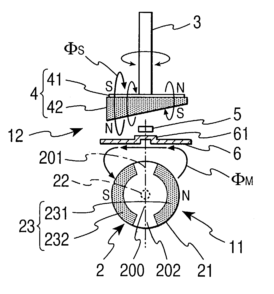
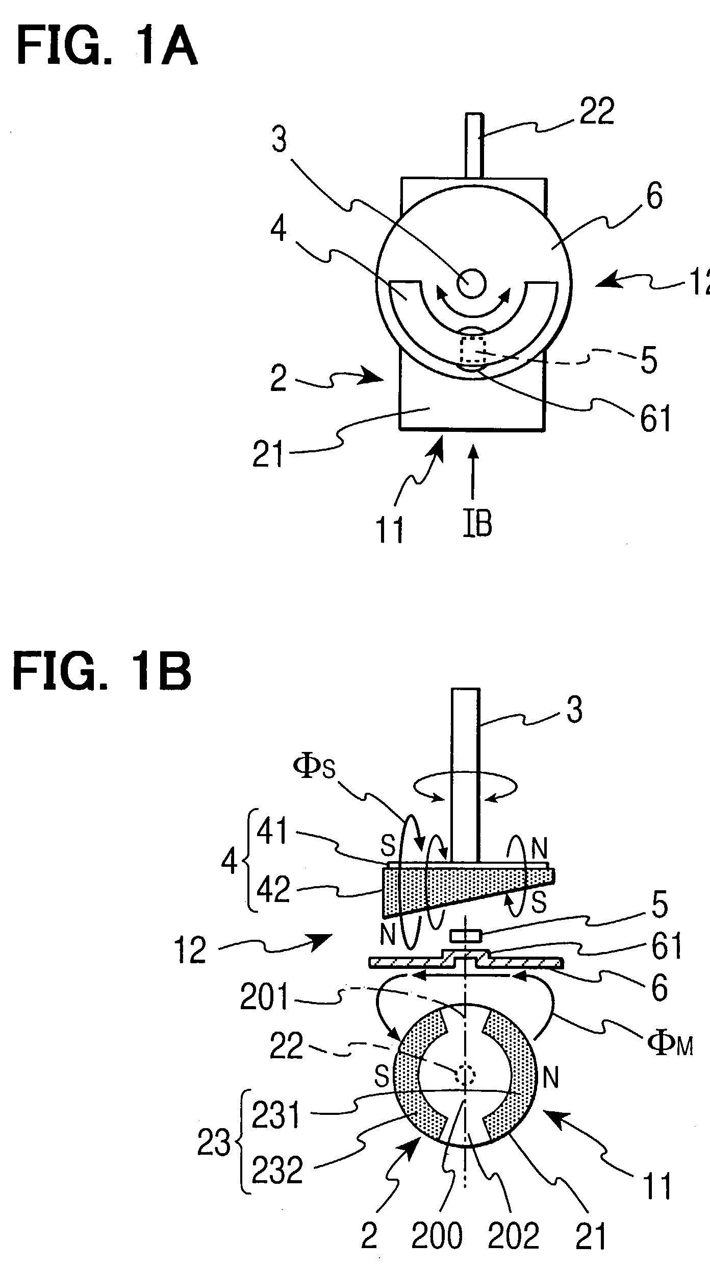
[0022] As shown in FIGS. 1A and 1B, a magnetic sensor unit 11, which is housed inside an actuator, has an actuator motor 2, which has a well-known motor structure, as a principal portion thereof. The actuator motor 2 has a cylindrical motor case 21 and a motor shaft 22. The motor shaft 22 projects in a center of one end surface of the case 21. Moreover, inside the motor case 21, the actuator motor 2 has a magnetic circuit including a pair of motor magnets 231, 232. Each cross section of the motor magnets 231, 232 has an arc-shape. Moreover, the motor magnets 231, 232 are disposed along an inner surface of the motor case 21 symmetrically in a circumferential direction of the motor shaft 22. For example, the magnets 231, 232 are made of a permanent magnet. The magnets 231, 232 are opposed each other in a diametrical direction of the motor shaft 22. A rotor (not shown) ...


PUM


Abstract

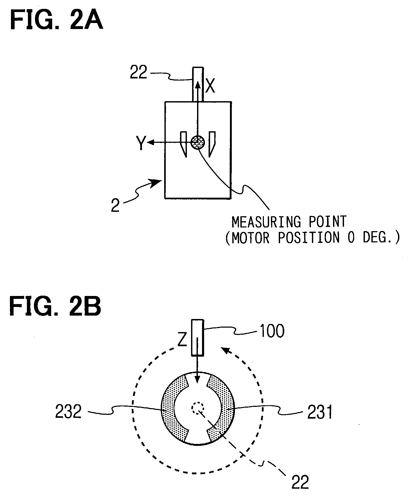
A magnetic sensor unit includes an actuator motor and a magnetic position sensor. The actuator motor has a magnetic circuit including motor magnets. The magnetic position sensor includes a sensor magnet and a hall element for detecting magnetic flux. Magnet clearances are formed between the motor magnets. The hall element is disposed outside of the motor to detect the magnetic flux in a direction penetrating through the magnet clearances, and which is perpendicular to a direction from one of the motor magnets to the other. In this disposition of the hall element, it is restricted that the hall element detects leaking magnetic flux from the motor magnets.

Description

CROSS REFFERENCE TO RELATED APPLICATION[0001] This application is based on Japanese Patent Application No. 2002-186017 filed on Jun. 26, 2002, the disclosure of which is incorporated herein by reference.[0002] 1. Field of the Invention[0003] The present invention relates to a magnetic sensor unit, which is principle system of an actuator for an automobile and installed in the actuator.[0004] 2. Description of Related Art[0005] A conventional magnetic sensor unit includes a magnetic circuit, for example, which converts electricity into driving force or torque. A position sensor is provided in the actuator that requires a precise driving mechanism, for example, the actuator for controlling intake valves of an engine of the automobile. The position sensor detects the rotating amount or the driving amount of members rotated or driven by the magnetic sensor unit. As a position detecting method of the position sensor, a magnetically detecting method, a contact resistance detecting method,...

Claims


Application Information

Patent Timeline
Patent Type & Authority Applications(United States)
IPC IPC(8): G01D5/18G01B7/00G01B7/30G01D5/12G01D5/14G01D9/12H02K11/01H02K11/21H02K11/215
CPCG01D5/145G01D2205/77
Inventor TOKUNAGA, MASAOTAKEDA, KENJIKAMIYA, TOMOMITSU
Owner NIPPON SOKEN
Learn More