
Packing apparatus for pressure type soil-nailing and soil-nailing construction method using the packing apparatus

a technology of packing apparatus and construction method, which is applied in the direction of soil preservation, bulkheads/piles, excavations, etc., can solve the problems of unavoidable development of steep slope districts, depreciation of construction efficiency, and longer construction period, so as to shorten construction term and improve construction efficiency

Inactive Publication Date: 2003-12-25
KOREA LAND COPORATION +2
View PDF1 Cites 15 Cited by
  • Summary
  • Abstract
  • Description
  • Claims
  • Application Information

AI Technical Summary

Benefits of technology

[0026] The present invention is proposed in order to solve the above-described problems. An object of the present invention is to provide a packing apparatus for pressure type soil-nailing and soil-nailing construction method using the packing apparatus which can shorten a construction term and improve construction efficiency by executing grouting at a situation which seals completely grouting area by injecting a quick forming expansion agent at the packing apparatus.
[0027] Another purpose of the present invention is provide to the packing apparatus for pressure type soil-nailing and soil-nailing construction method using the packing apparatus which is suitable for improving stability of ground reinforcements by filling liquid grout to even a gap between the boring hole and the ground and void of the ground through pressure type soil-nailing.

Problems solved by technology

Generally, according to industrial development, it is unavoidable situation to develop a steep slope district such as a mountain district by production of housing complex or construction of new city, etc.
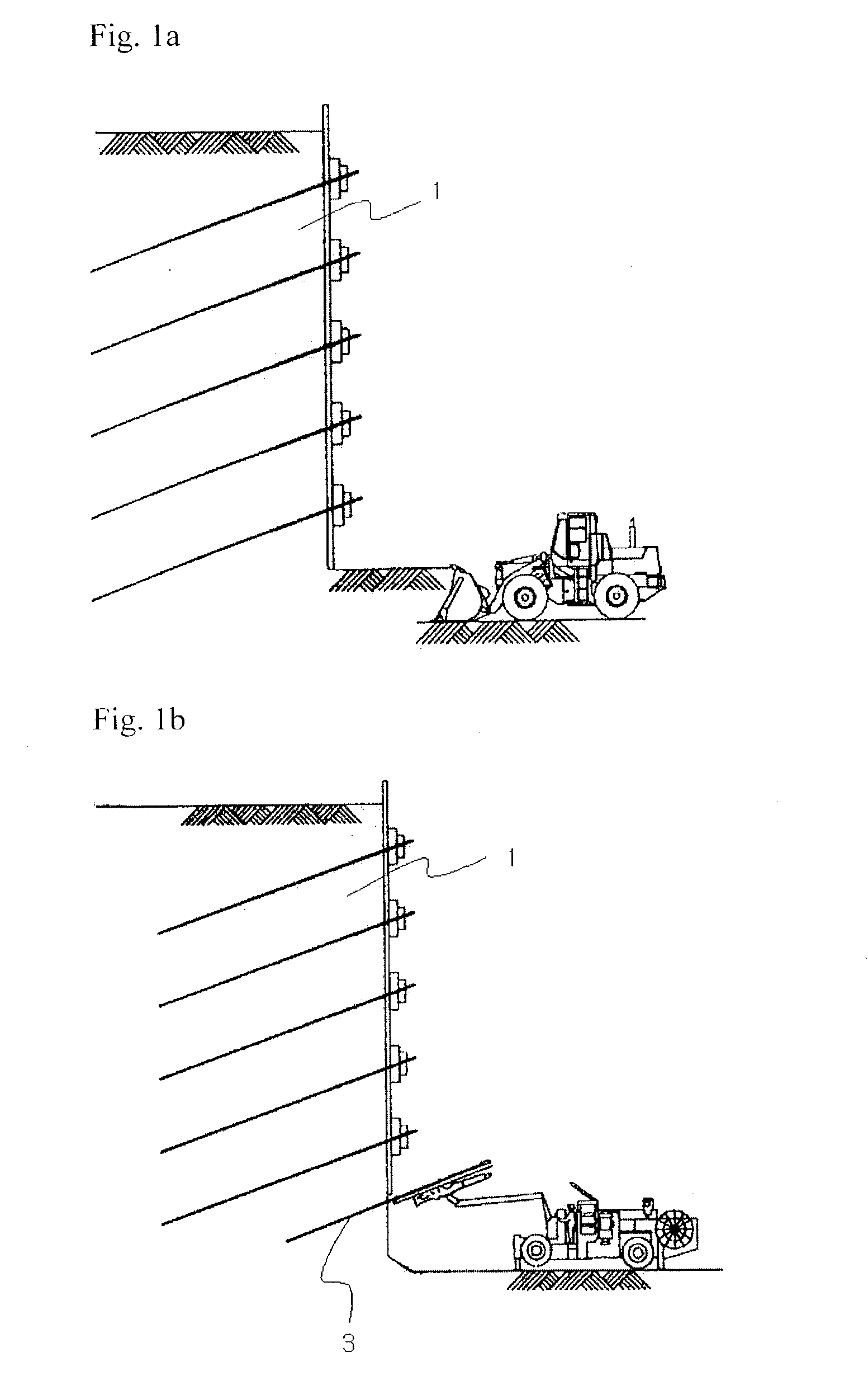
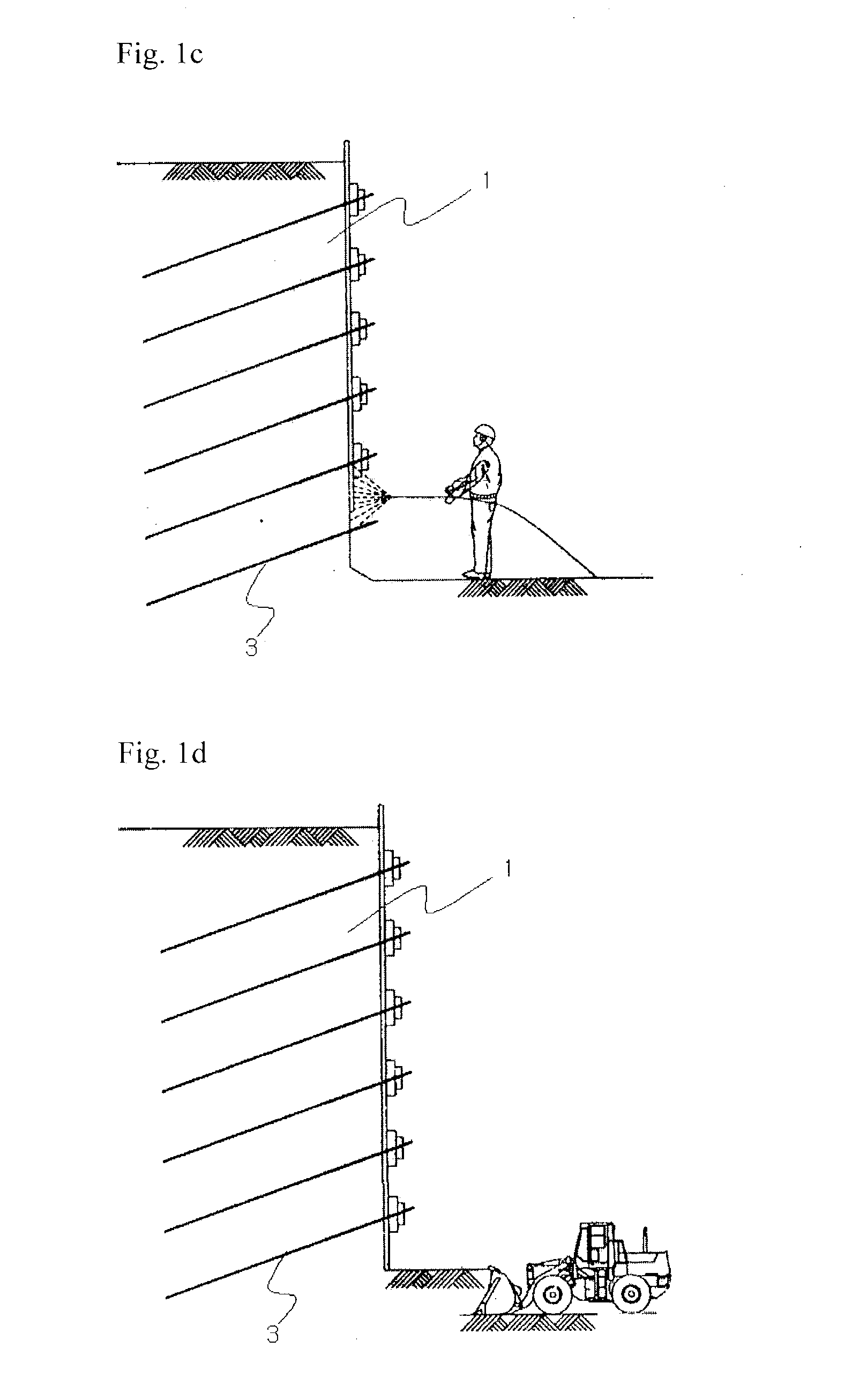
However, because such conventional soil-nailing construction method adapts gravity type grouting, solidifying time is long and grouting should be repeated about 3.about.6 times in order to supplement contraction phenomenon.
Thereby, because conventional soil-nailing construction method prolongs the process, construction efficiency is depreciated, thus there was a problem that construction period becomes longer.
Also, because the bored hole is slanted downwardly, it is impossible to fill liquid grout in grouting area, a gap between the boring hole and the ground is produced, whereby there was a problem to provoke a fatal defect at ground reinforcements.

Method used


Image

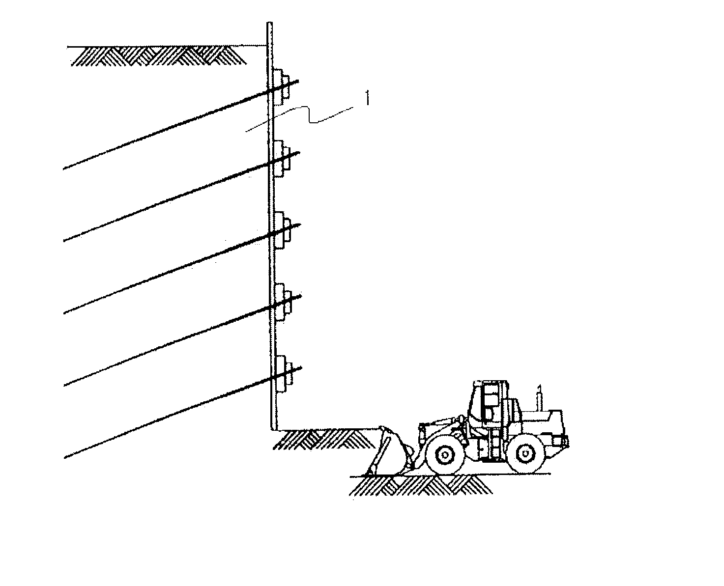
  • Packing apparatus for pressure type soil-nailing and soil-nailing construction method using the packing apparatus
  • Packing apparatus for pressure type soil-nailing and soil-nailing construction method using the packing apparatus
  • Packing apparatus for pressure type soil-nailing and soil-nailing construction method using the packing apparatus

Examples


Embodiment Construction

[0039] Below, the packing apparatus for pressure type soil-nailing of the present invention as described above will be explained in detail with reference to the accompanying drawings.

[0040] FIG. 3 is a perspective view of the packing apparatus for pressure type soil-nailing of the present invention, FIG. 4 is a perspective view with parts taken away of the packing apparatus for pressure type soil-nailing of the present invention, and FIG. 5 is a cross section of the ground for explaining the establishment state of the packing apparatus for pressure type soil-nailing of the present invention.

[0041] As illustrated to drawings, at the packing apparatus for pressure type soil-nailing of the present invention are inserted the first packing 33a and the second packing 33b at a predetermined interval mutually to a lengthwise direction of the nail 31 in which screw threads are formed on the circumferential surface.

[0042] Also, at the packing apparatus for pressure type soil-nailing of the pr...


PUM


Abstract

The present invention relates to a packing apparatus for pressure type soil-nailing and soil-nailing construction method using the apparatus, can shorten a grouting time through pressure type grouting which seals completely grouting area, and can improve stability of a ground reinforcing body by filling liquid grout to even a gap between a boring hole and the ground and void of the ground.

Description

[0001] The present invention relates to a packing apparatus for pressure type soil-nailing and soil-nailing construction method using the packing apparatus. More specifically, the invention relates to a packing apparatus for pressure type soil-nailing and soil-nailing construction method using the packing apparatus which is suitable for sealing closely grouting area which is formed in a bored hole and improving construction efficiency through grouting by pressure, that is, filling pressuringly of liquid grout.BACKGROUND OF INVENTION[0002] Generally, according to industrial development, it is unavoidable situation to develop a steep slope district such as a mountain district by production of housing complex or construction of new city, etc.[0003] Accordingly, it is required to provide a construction method for slope stability that can satisfy construction efficiency, economical efficiency and preservation efficiency of environment as well as heighten an availability of land and secur...

Claims


Application Information

Patent Timeline
IPC IPC(8): E02D5/76E02D17/04E02D17/20E02D3/12
CPCE02D5/76E02D5/80E21D21/00
Inventor LEE, MYUNG-JAE
Owner KOREA LAND COPORATION
Learn More