Potential energy surface sensor chip and use of potential energy surfaces on a sensor chip and method for preventing a sensor chip from being soiled

a sensor chip and potential energy surface technology, applied in the direction of instruments, heat measurement, liquid/fluent solid measurement, etc., can solve the problems of unfavorable influence, unsatisfactory influence, and distorting effect of measured signal

Inactive Publication Date: 2003-08-28
ROBERT BOSCH GMBH
View PDF8 Cites 7 Cited by
  • Summary
  • Abstract
  • Description
  • Claims
  • Application Information

AI Technical Summary

Benefits of technology

[0009] The sensor chip according to the present invention having the potential surfaces and the use according to the present invention of potential surfaces on a sensor chip and the method according to the present invention for avoiding contaminants on a sensor chip, having the characterizing features of claims 1, 13, and 14 and 15, respectively, have, in contrast, the advantage that contamination of the sensor chip is reduced or prevented in a simple fashion.[0010] The actions set forth in the dependent claims make possible advantageous developments of and improvements to the sensor chip recited in claim 1.[0011] Advantageously, potential surfaces that protect the sensor region e.g. in the event of backflows are also positioned downstream from the sensor region.[0012] An advantageous potential drop is achieved by way of a positive potential on a first potential surface and a negative potential on a subsequent potential surface.[0013] The potential surfaces advantageously have a U-shape which advantageously surrounds the sensor region.[0014] The potential surfaces are advantageously embodied, like the heating resistors, as a conductor path, since this is a known and simple manufacturing method.[0015] The sensor region is advantageously operated independently of the potential surfaces, i.e. the measurement or the measured signal supplied by the sensor region is not influenced by operation of the potential surfaces, and vice versa.

Problems solved by technology

Contaminants, for example oil, to which the sensor chip is exposed can at any time result in an undesirable influence on the measured signal of the sensor chip in the vicinity of the sensor region.
Contamination with oil of the sensor region, or in the immediate vicinity around the sensor region, modifies the thermal conductivity on the surface of the sensor chip and thus has a distorting effect on the measured signal.
These captured particles in turn additionally enhance the unfavorable influence.

Method used


Image

  • Potential energy surface sensor chip and use of potential energy surfaces on a sensor chip and method for preventing a sensor chip from being soiled
  • Potential energy surface sensor chip and use of potential energy surfaces on a sensor chip and method for preventing a sensor chip from being soiled

Examples


Embodiment Construction

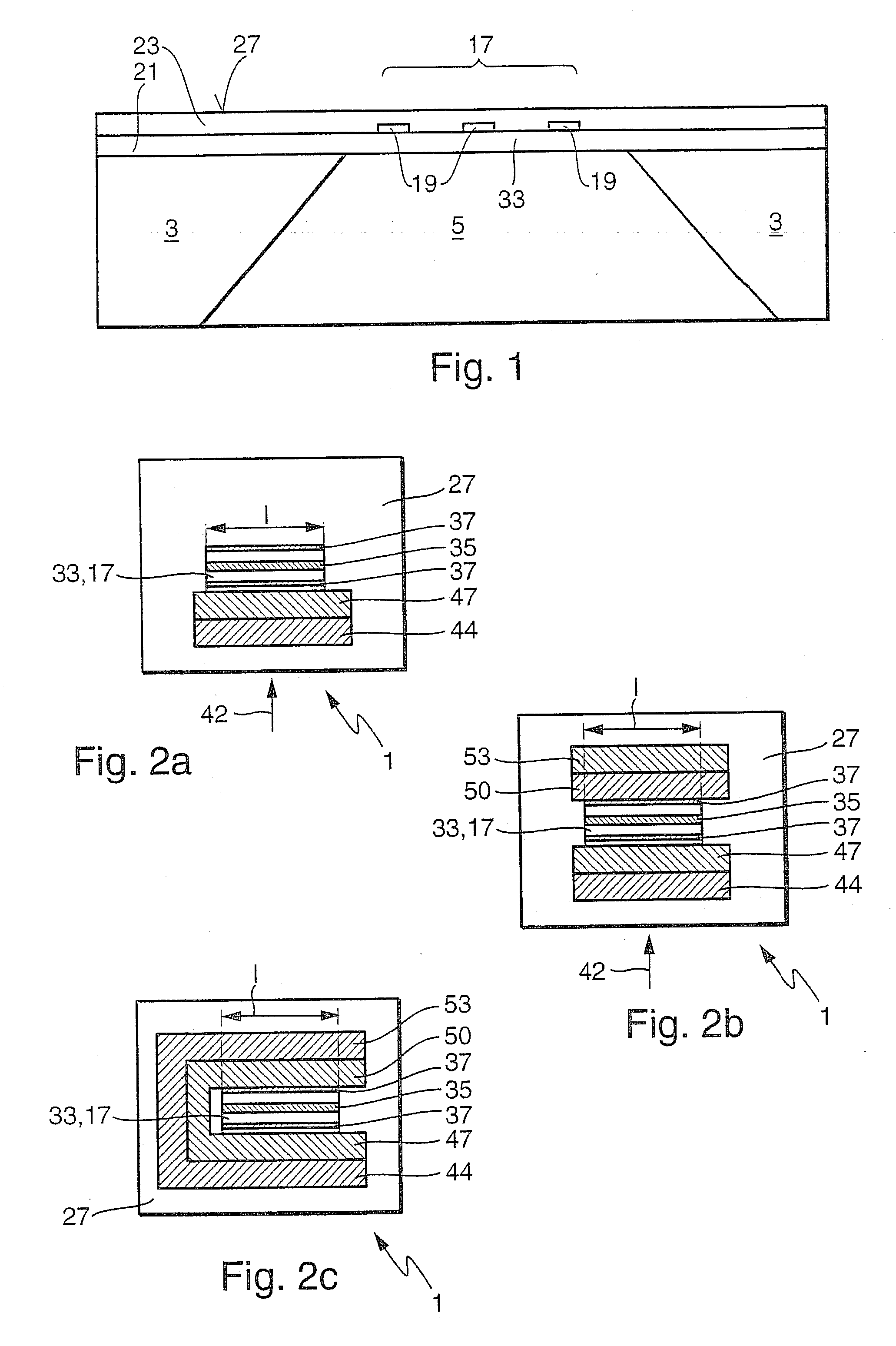
[0019] FIG. 1 shows a sensor chip according to the existing art that is improved according to the present invention in accordance with the remarks referring to FIGS. 2a through 2c. The manufacturing method and application of such a sensor chip are described in more detail in DE 196 01 791 A1, the content of which is explicitly intended to be part of this disclosure.

[0020] The sensor chip has a frame element 3 that is made, for example, of silicon. Frame element 3 has a recess 5. Mounted on the frame element is, for example, a dielectric layer 21 made e.g. of SiO.sub.2. Layer 21 can extend over the entire frame element 3, but also over only a region of recess 5. This region constitutes a membrane 33 that partially or entirely delimits recess 5 on one side. Mounted on the side of membrane 33 facing away from recess 5 are at least one, for example three, metal paths 19. Metal paths 19 constitute e.g. electrical heaters and / or measurement resistors, and with membrane 33 constitute a sen...


PUM

PropertyMeasurementUnit
potential surfaceaaaaaaaaaa
distanceaaaaaaaaaa
electrical potentialaaaaaaaaaa

Abstract

In a sensor chip according to the existing art, contaminants in the medium flowing past the sensor chip result in deposits in the sensor region. A sensor chip (1) according to the present invention has, at least upstream from the sensor region (17), at least one potential surface (44, 47, 50, 53) that, by electrical interaction with the contaminants in the flowing medium, prevents precipitation in the sensor region (17).

Description

BACKGROUND INFORMATION[0001] The invention proceeds from a sensor chip having potential surfaces, and from a use of a potential surface on a sensor chip, and from a method for avoiding contaminants on a sensor, according to the species defined in claims 1, 13, and 14 and 15, respectively.[0002] DE 196 01 791 A1 has disclosed a sensor chip having a sensor region that is made up, for example, of a frame element, a recess, and a membrane that forms a sensor region. Contaminants, for example oil, to which the sensor chip is exposed can at any time result in an undesirable influence on the measured signal of the sensor chip in the vicinity of the sensor region. Contamination with oil of the sensor region, or in the immediate vicinity around the sensor region, modifies the thermal conductivity on the surface of the sensor chip and thus has a distorting effect on the measured signal. In addition, oil deposited on the sensor chip serves as an adhesion promoter for solid particles contained ...

Claims


Application Information

Patent Timeline
Patent Type & Authority Applications(United States)
IPC IPC(8): G01F1/684G01P5/12G01F1/692G01K7/18
CPCG01F1/6845G01F1/684
Inventor KONZELMANN, UWESCHULZ, TORSTEN
Owner ROBERT BOSCH GMBH
Why Eureka
Try Eureka