
Expansion joint cover

a technology of expansion joints and covers, applied in the direction of resiliently-mounted floors, flooring, ways, etc., can solve the problems of inability to effectively accommodate the variations of lateral offset and torsion between the two surfaces, rigid materials sometimes experience failures when they expand or contract, and are typically not aesthetically appealing

Inactive Publication Date: 2003-08-21
BALCO
View PDF0 Cites 3 Cited by
  • Summary
  • Abstract
  • Description
  • Claims
  • Application Information

AI Technical Summary

Benefits of technology

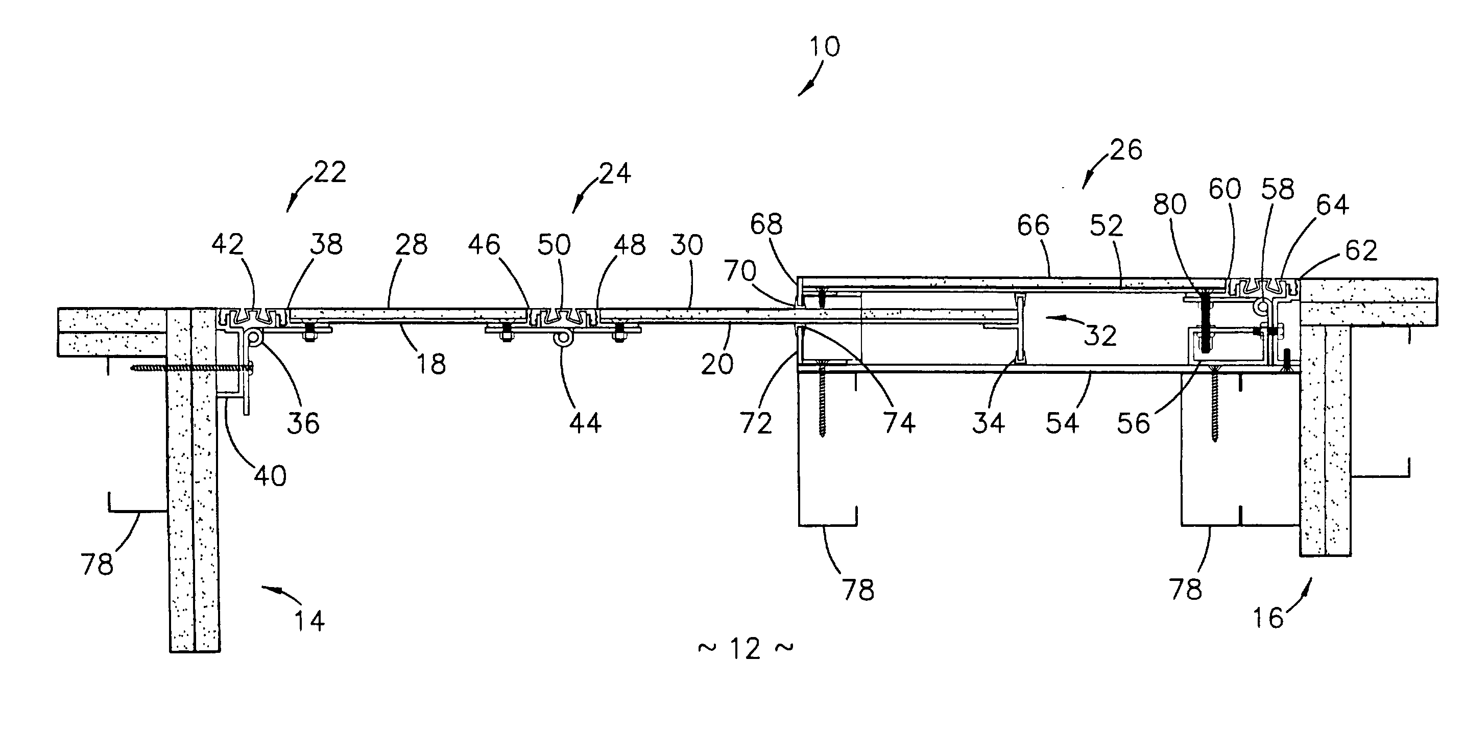
[0013] The expansion joint cover is preferably used to cover an expansion joint comprising a first surface and a second surface. The preferred embodiment of the expansion joint cover broadly comprises a first plate, a second plate, a first hinge assembly hingedly attaching the first plate to the first surface, a second hinge assembly hingedly attaching the first plate to the second plate, and a housing fixedly secured to the second surface. The first plate includes an exterior surface, where a facade can be secured, in order to enhance aesthetic appeal of the expansion joint cover.
[0018] Alternatively, the housing may include only a front plate, a rear plate, and a bracket. The front plate and the rear plate would include the standoffs and low friction seals discussed above. The bracket may be a separate component that is attached, affixed, or integral to the rear plate. The front plate is secured to the bracket using mechanical fasteners, adhesives, tapes, and / or welds. This would negate the need for the tension block, the hinge, and the face seal.

Problems solved by technology

Unfortunately, such rigid materials sometimes experience failures when they expand or contract due to changing temperatures or when they move due to seismic events.
While the flexible material may effectively seal the expansion joint, it is typically not aesthetically appealing and therefore is often covered.
These designs cannot effectively accommodate variations in lateral offset and torsion between the two surfaces.
However, the internal dimensions of the housing limit the allowable lateral offset and torsion between the two surfaces.
However, the internal dimensions of the housing still limit allowable lateral offset between the two surfaces.

Method used


Image

  • Expansion joint cover
  • Expansion joint cover
  • Expansion joint cover

Examples


Embodiment Construction

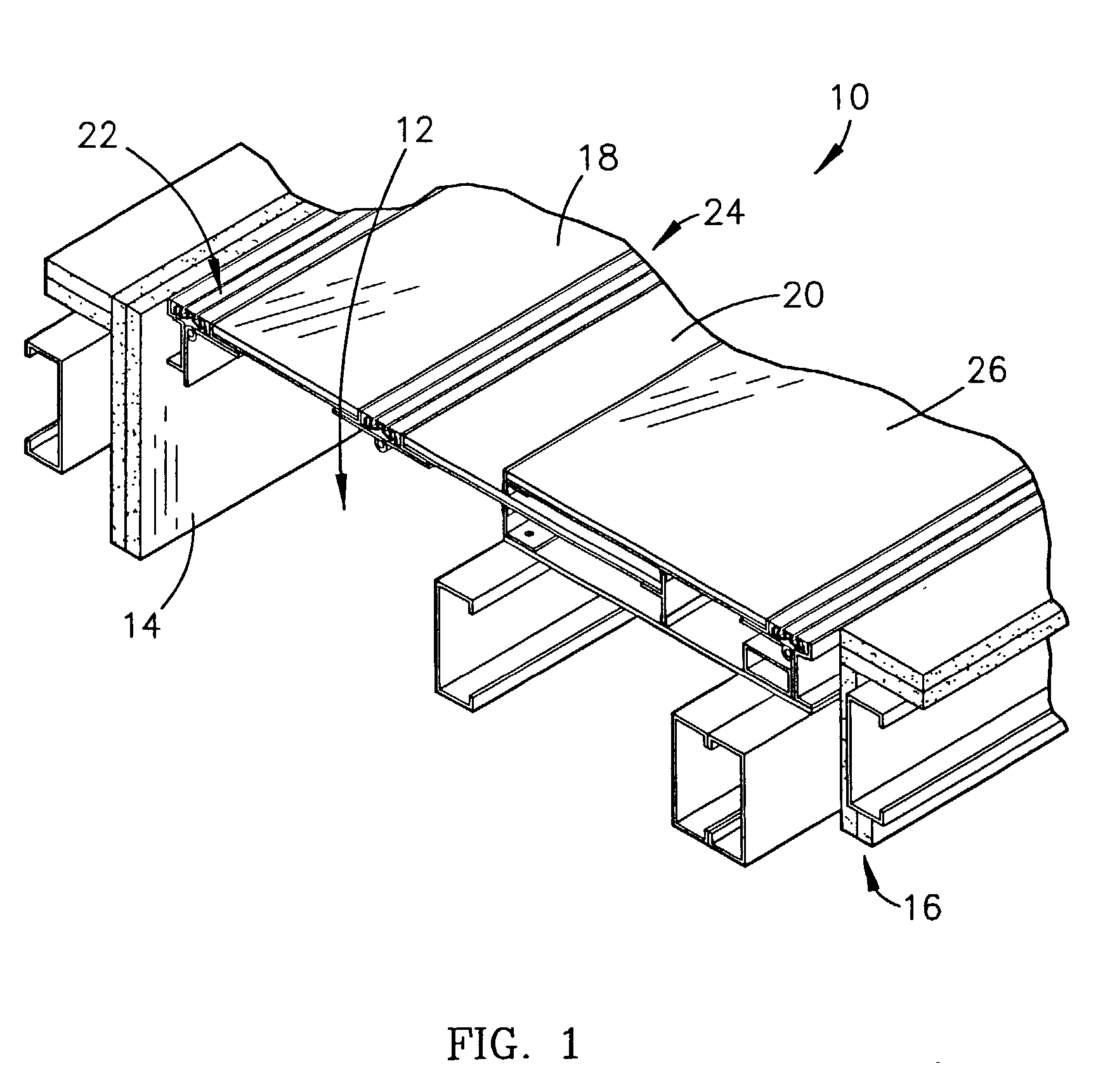
[0025] Referring to FIG. 1, an expansion joint cover 10 is shown constructed in accordance with a preferred embodiment of the present invention. The cover 10 is used to cover an expansion joint 12 between a first surface 14 and a second surface 16 of a building or other structure. The surfaces 14,16 can have similar or different configurations and textures and may be parallel, perpendicular, or otherwise situated relative to each other.

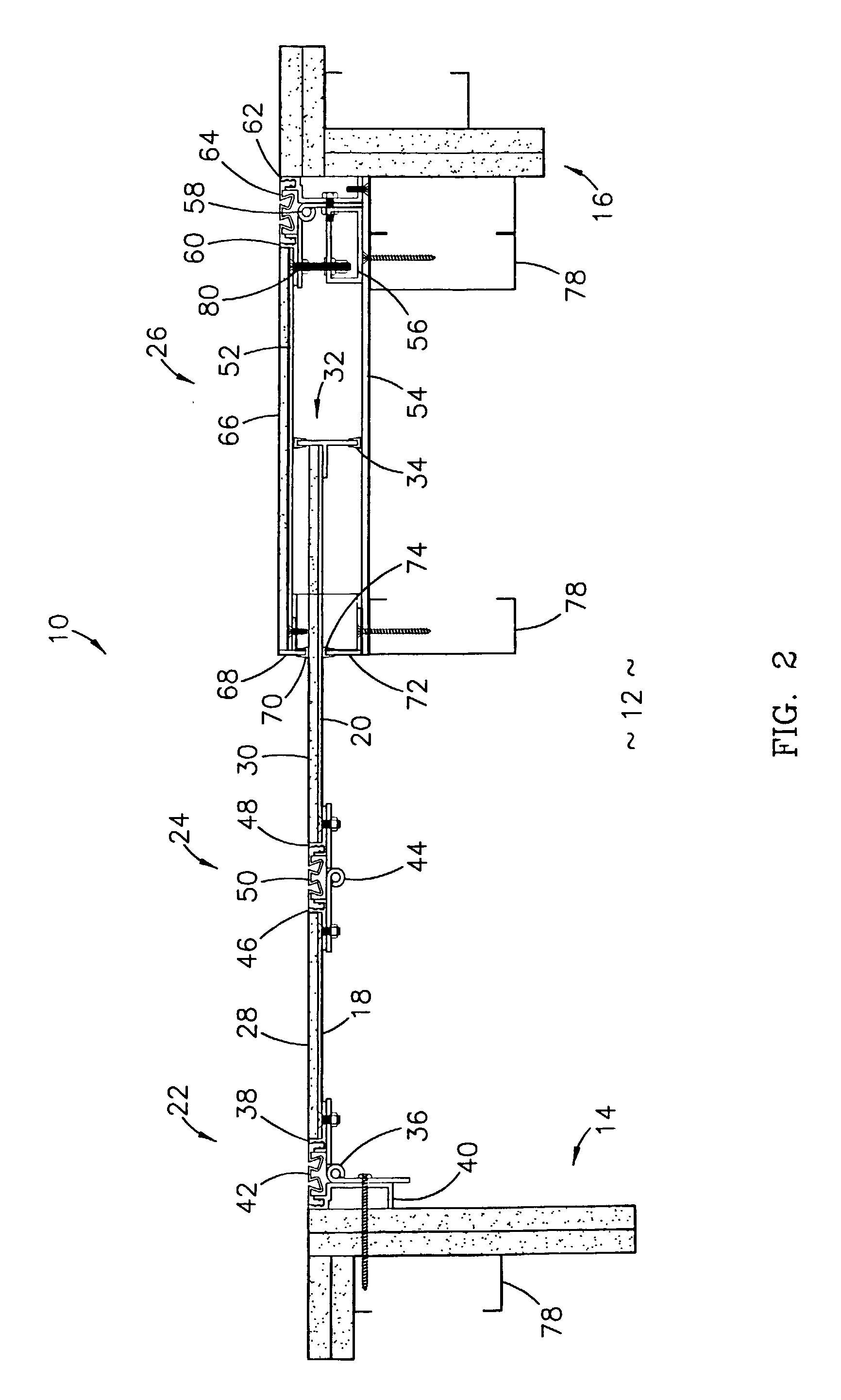
[0026] Referring also to FIG. 2, the preferred expansion joint cover 10 broadly comprises a first plate 18, a second plate 20, a first hinge assembly 22 hingedly attaching the first plate 18 to the first surface 14, a second hinge assembly 24 hingedly attaching the first plate 18 to the second plate 20, and a housing 26 fixedly secured to the second surface 16. The first plate 18 is preferably constructed of steel, but can be constructed of any rigid material. The first plate 18 includes an exterior surface, where a facade 28 can be secured, in order ...


PUM


Abstract

An expansion joint cover (10) comprises a first plate (18) hingedly attached to a first surface (14) of an expansion joint (12), a second plate (20) hingedly attached to the first plate (18), and a housing (26) fixedly secured to a second surface (16) of the expansion joint (12). During installation, a front plate (52) of the housing (26) can rotate about a hinge (58) to allow the second plate (20) to be installed within the housing (26). In use, the second plate (20) slides within the housing (26) to accommodate variations in separation distance and vertical offset between the two surfaces (14,16). Two hinges (36,44) accommodate variations in torsion between the two surfaces (14,16). The combination of the second plate (20) sliding within the housing (26) and the two hinges (36,44) accommodates variations in lateral offset between the two surfaces (14,16).

Description

[0001] This application is related to and claims priority benefit of a co-pending patent application entitled "Expansion Joint Cover,"Ser. No. 10 / 078,079, filed Feb. 15, 2002, which is hereby incorporated into the present invention by reference.[0002] 1. Field of the Invention[0003] The present invention relates to expansion joints and expansion joint covers. More particularly, the present invention relates to an expansion joint cover that can accommodate variations in separation distance, vertical offset, lateral offset, and torsion between two surfaces of an expansion joint.[0004] 2. Description of Prior Art[0005] Buildings are typically constructed of rigid materials such as concrete and steel which are chosen for their ability to support loads and resist movement under those loads. Unfortunately, such rigid materials sometimes experience failures when they expand or contract due to changing temperatures or when they move due to seismic events.[0006] To prevent failures, it is co...

Claims


Application Information

Patent Timeline
Patent Type & Authority Applications(United States)
IPC IPC(8): E04B1/68E04B1/686E04F15/02E04F19/02
CPCE04B1/6815E04F19/02E04F15/02005
Inventor KNAK, RONNY L.BALOCCA, DEAN V.HILBURN, JOHNNIE D.
Owner BALCO
Learn More