
Attitude angle detecting apparatus

a detection apparatus and attitude angle technology, applied in the direction of speed measurement using gyroscopic effects, instruments, wave based measurement systems, etc., can solve the problems of inability to immediately obtain the attitude angles, significant influence on the degree of deterioration of the estimated attitude angles, and inability of the above-mentioned apparatus to measure carrier phases, etc., to achieve the effect of determining the integer ambiguity quickly and accurately

Inactive Publication Date: 2003-08-14
FURUNO ELECTRIC CO LTD
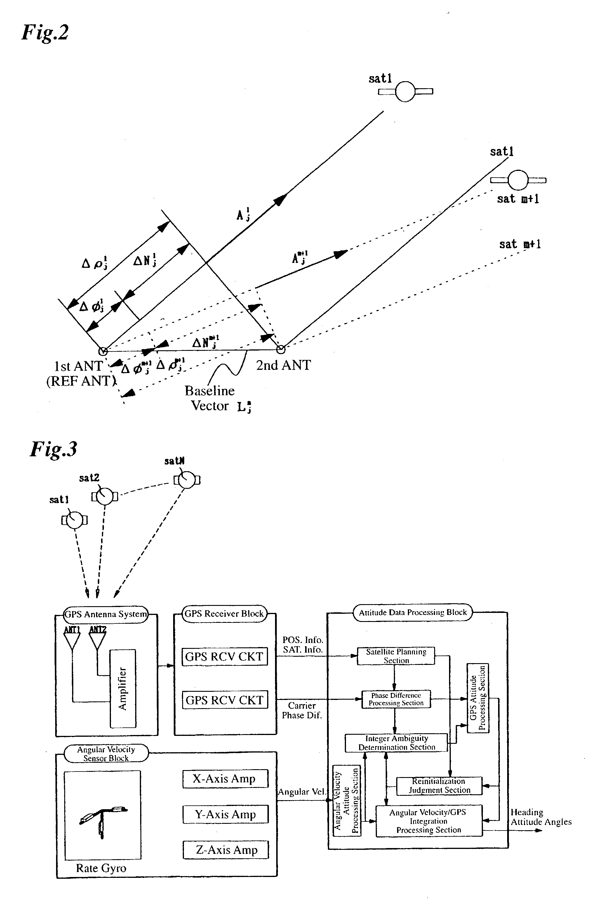
View PDF4 Cites 37 Cited by
  • Summary
  • Abstract
  • Description
  • Claims
  • Application Information

AI Technical Summary

Benefits of technology

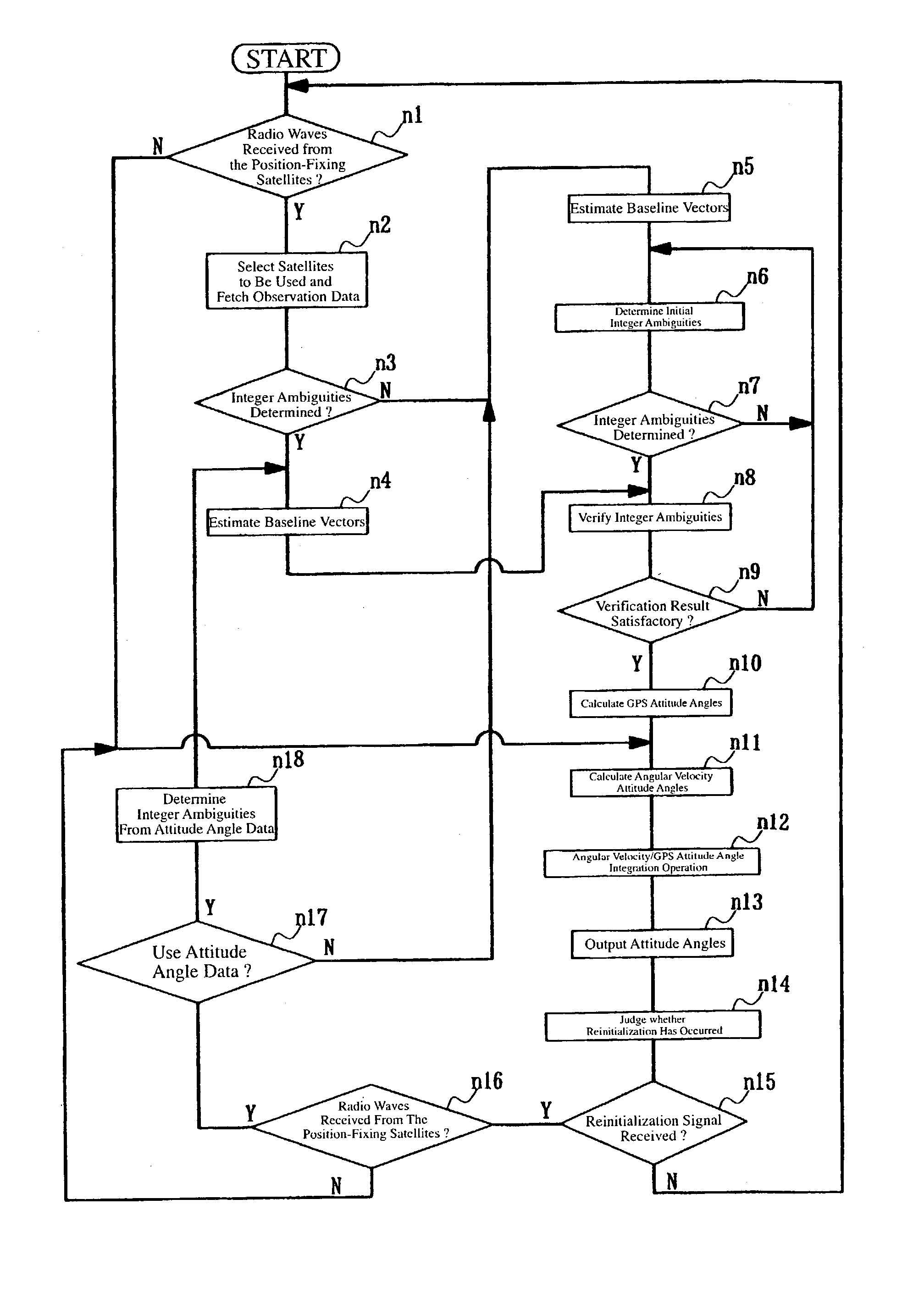
[0019] Since the attitude angles and the attitude angle error covariance are used in producing the integer ambiguity candidates, it is possible to redetermine the integer ambiguity from the single or double phase difference for measuring the relative positions of the antennas quickly and accurately when it is necessary to redetermine the integer ambiguity after recovery from an interruption of radio waves from position-fixing satellites of the Global Positioning System (GPS).
[0022] With this arrangement, it is possible to redetermine the integer ambiguity quickly and accurately under various conditions by making a specific correction to the attitude angles and the error covariance of the attitude angles.
[0027] By using an angular velocity sensor or an assumed model as the means for calculating the attitude angles of the mobile unit and the error covariance of the attitude angles as stated above, the apparatus can determine the integer ambiguity quickly and accurately.

Problems solved by technology

If the radio waves from some of the position-fixing satellites are interrupted by some external obstacle, for example, it becomes impossible for the aforementioned apparatus to measure carrier phases and continue estimation of the heading and attitude (hereinafter referred to as attitude angles implying both) of the mobile unit.
Although the apparatus resumes operation for determining carrier phase ambiguities based on the radio waves from the position-fixing satellites again when it becomes possible to receive the radio waves, it is not possible to instantly obtain the attitude angles, because it takes time to redetermine the carrier phase ambiguities.
The degree of deterioration of the estimated attitude angles is considerably affected by measurement errors of the angular velocity sensor.
It is likely that integer ambiguity candidates calculated from estimated values of attitude angles containing such errors do not agree with the true integer ambiguity.
The conventional attitude angle detecting apparatus has a potential to incorrectly determine integer ambiguity candidates and provide wrong attitude angles as mentioned above.

Method used


Image

  • Attitude angle detecting apparatus
  • Attitude angle detecting apparatus
  • Attitude angle detecting apparatus

Examples


Embodiment Construction

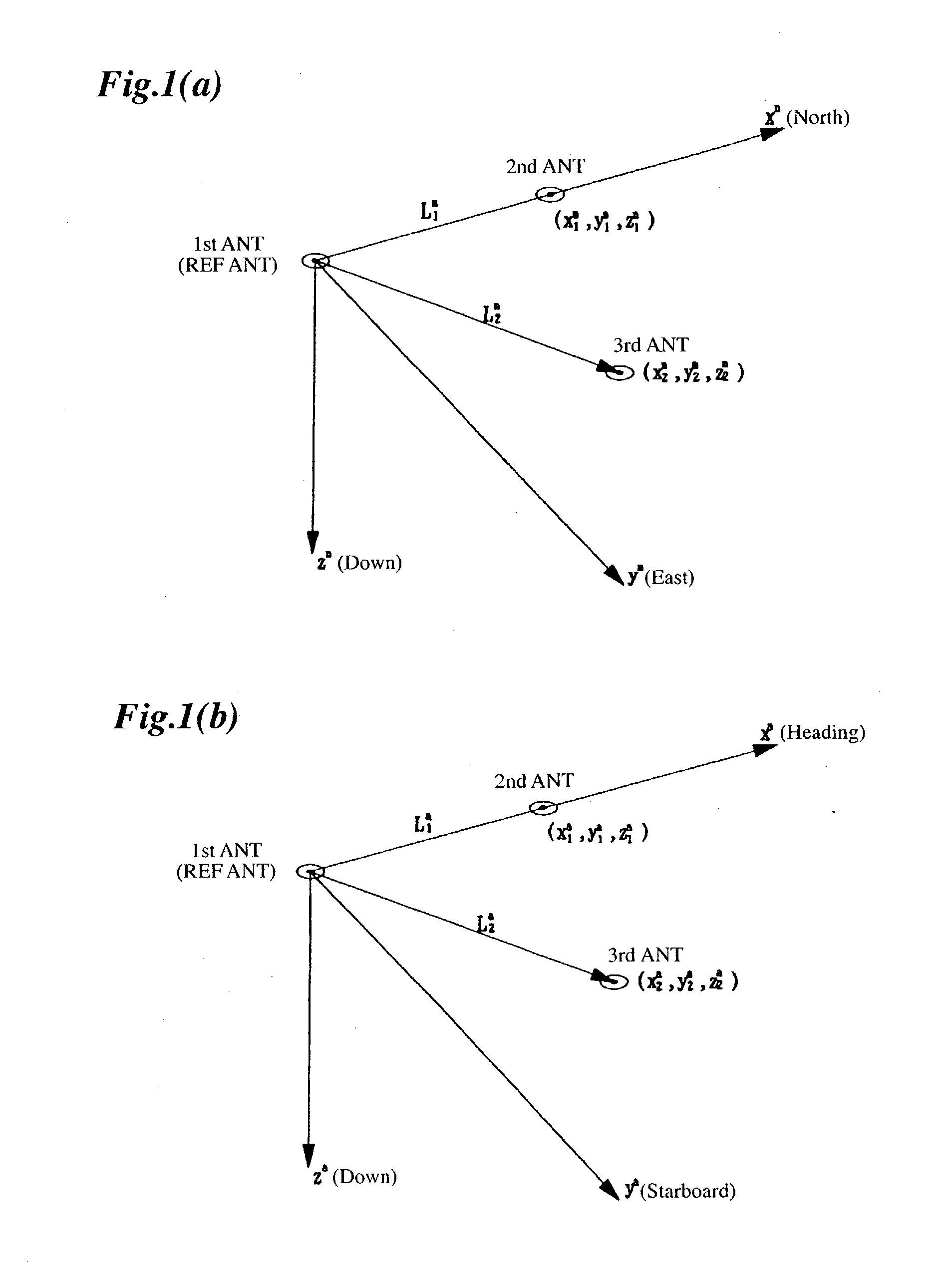
[0038] First, an antenna coordinate system, a local coordinate system and coordinate transformation between these two coordinate systems are explained referring to FIGS. 1A and 1B.

[0039] FIG. 1A shows an antenna layout depicted in the local coordinate system, in which the x, y and z axes represent north, east and vertical directions, respectively, with the position of a reference antenna (first antenna) located at an origin, for instance.

[0040] In FIG. 1A, a point shown by coordinates (x.sub.1.sup.n, y.sub.1.sup.n, z.sub.1.sup.n) is the position of a second antenna, a point shown by coordinates (x.sub.2.sup.n, y.sub.2.sup.n, z.sub.2.sup.n) is the position of a third antenna, L.sub.1.sup.n is a baseline vector taken from the first antenna to the second antenna, and L.sub.2.sup.n is a baseline vector taken from the first antenna to the third antenna. The superscript "n" written to the right of the values of the coordinates and the baseline vectors indicates that these coordinates and ...


PUM


Abstract

An attitude angle detecting apparatus receives radio waves transmitted from a plurality of position-fixing satellites with multiple antennas located at specific positions of a mobile unit, determines relative positions of the antennas and detects the heading and attitude of the mobile unit by determining carrier phase ambiguities quickly and accurately. When it is needed to redetermine integer ambiguities after recovery from an interruption of the radio waves from the position-fixing satellites or as a result of a change in combination of the position-fixing satellites, for example, the attitude angle detecting apparatus redetermines the integer ambiguities by using attitude angles and an attitude angle error covariance obtained from previous observation. This enables the attitude angle detecting apparatus to uninterruptedly obtain information on the heading and attitude of the mobile unit.

Description

[0001] 1. Field of the Invention[0002] This invention relates to an attitude angle detecting apparatus for detecting the heading and attitude of a mobile unit, such as an aircraft or a ship.[0003] 2. Description of the Prior Art[0004] There exist conventionally used attitude angle detecting apparatus for detecting the heading and attitude of a mobile unit.[0005] One type of such apparatus receives radio waves transmitted from a plurality of position-fixing satellites with multiple antennas located at specific positions of a mobile unit, one of the antennas being used as a reference antenna, measures phases of carrier signals of the radio waves, and determines relative positions of the antennas other than the reference antenna with respect to the reference antenna to determine the heading and attitude of a mobile unit.[0006] Another type of such apparatus determines the attitude of a mobile unit by use of an angular velocity sensor like a rate gyro for measuring the turning rate of a...

Claims


Application Information

Patent Timeline
IPC IPC(8): G01C19/00G01S19/55
CPCG01S19/55
Inventor TODA, HIROYUKI
Owner FURUNO ELECTRIC CO LTD
Learn More