
Cooperative planning system and method

Inactive Publication Date: 2003-06-05
THE JOHN HOPKINS UNIV SCHOOL OF MEDICINE
View PDF12 Cites 43 Cited by
  • Summary
  • Abstract
  • Description
  • Claims
  • Application Information

AI Technical Summary

Problems solved by technology

Thus, for a patient living in a rural or remote area, travel to a larger city on a daily basis for an extended period of time can be time-consuming and physically taxing.
Further, frequently such patients are debilitated to some degree due to the illness for which they are receiving treatment, and may require the assistance of a support person, such as a family member, to get to and from the medical facility.
This can make it even more difficult for the patient to obtain treatment.
This remote method of treatment, while providing advantages to the patient, is inhibiting to the medical personnel involved in the planning and care delivery, since they often cannot meet in person for their collaborative efforts.
While this method works adequately, each collaborator is viewing his or her own set of documents, images, etc., leading to the possibility that one or more of the collaborators is viewing the wrong document or a degraded version of the original.
These systems allow the physician and other persons who may be working with the physician to view electronic versions of documents (e.g., a patient file or an MRI scan) while communicating with the patient While such methods do assist the physician and other medical personnel in remotely conducting collaborative efforts, these methods suffer from the same, previously-described problems.
In addition, because they may be viewing copies of a document, the document itself may suffer from degradation due to the copying process, and therefore not be an accurate representation of what it is supposed to be portraying.
Further, it may be difficult for the various participants to articulate to the other parties the location of a particular element in an image that they are viewing and discussing, since activity (e.g., movement of a pointer) on a computer at one location is not replicated or viewable at other locations.

Method used


Image

  • Cooperative planning system and method
  • Cooperative planning system and method
  • Cooperative planning system and method

Examples


Embodiment Construction

)

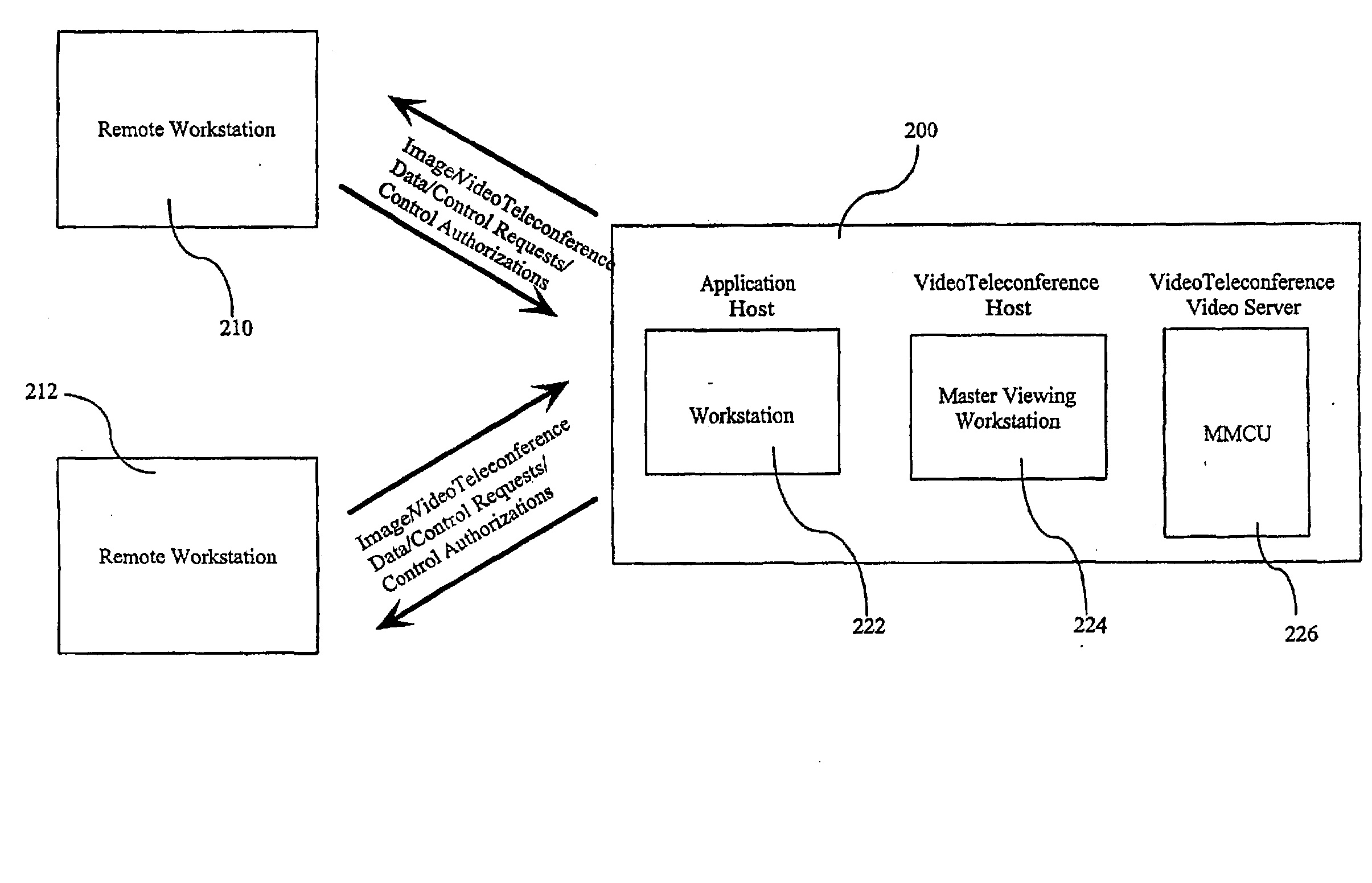
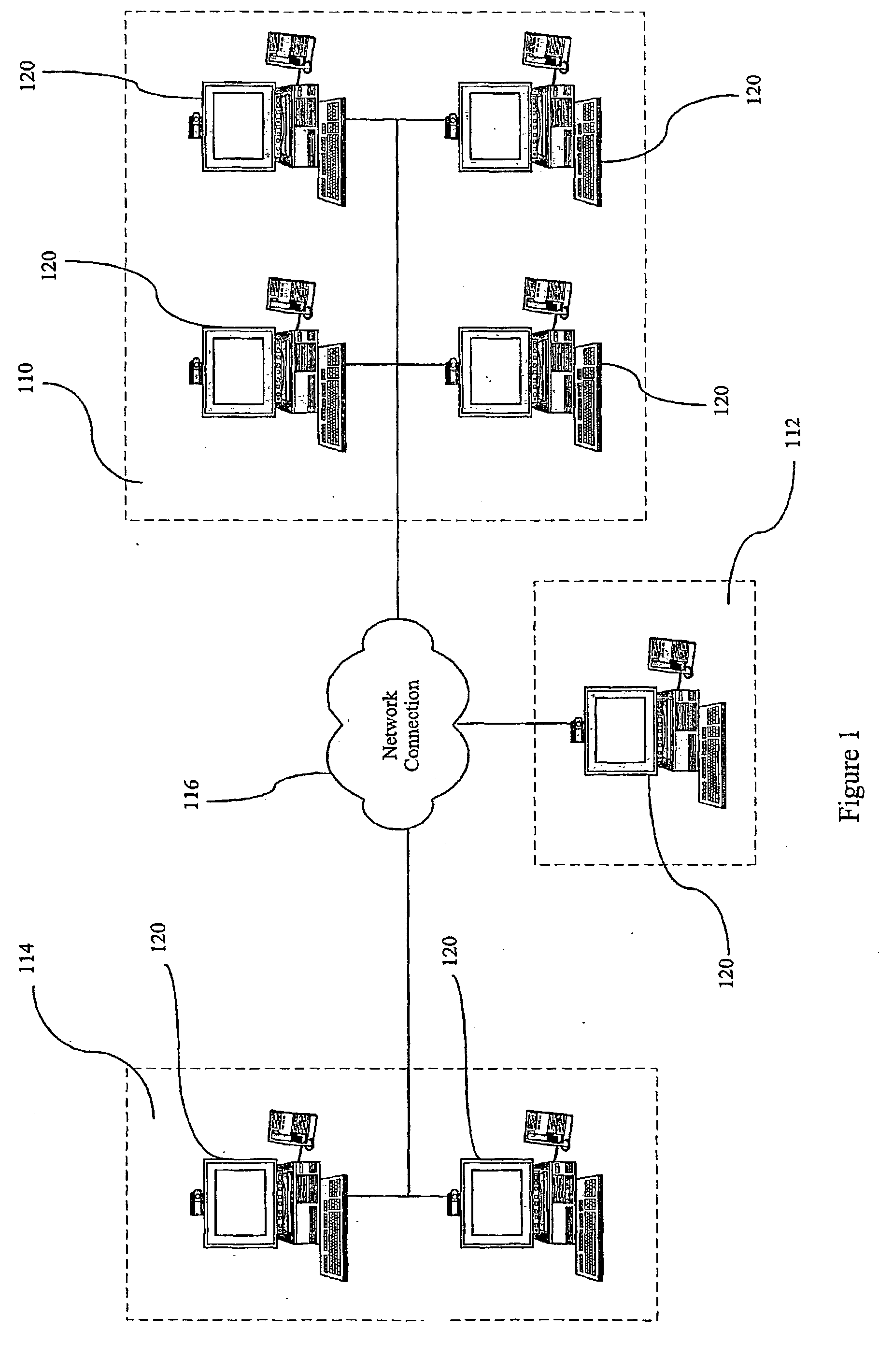
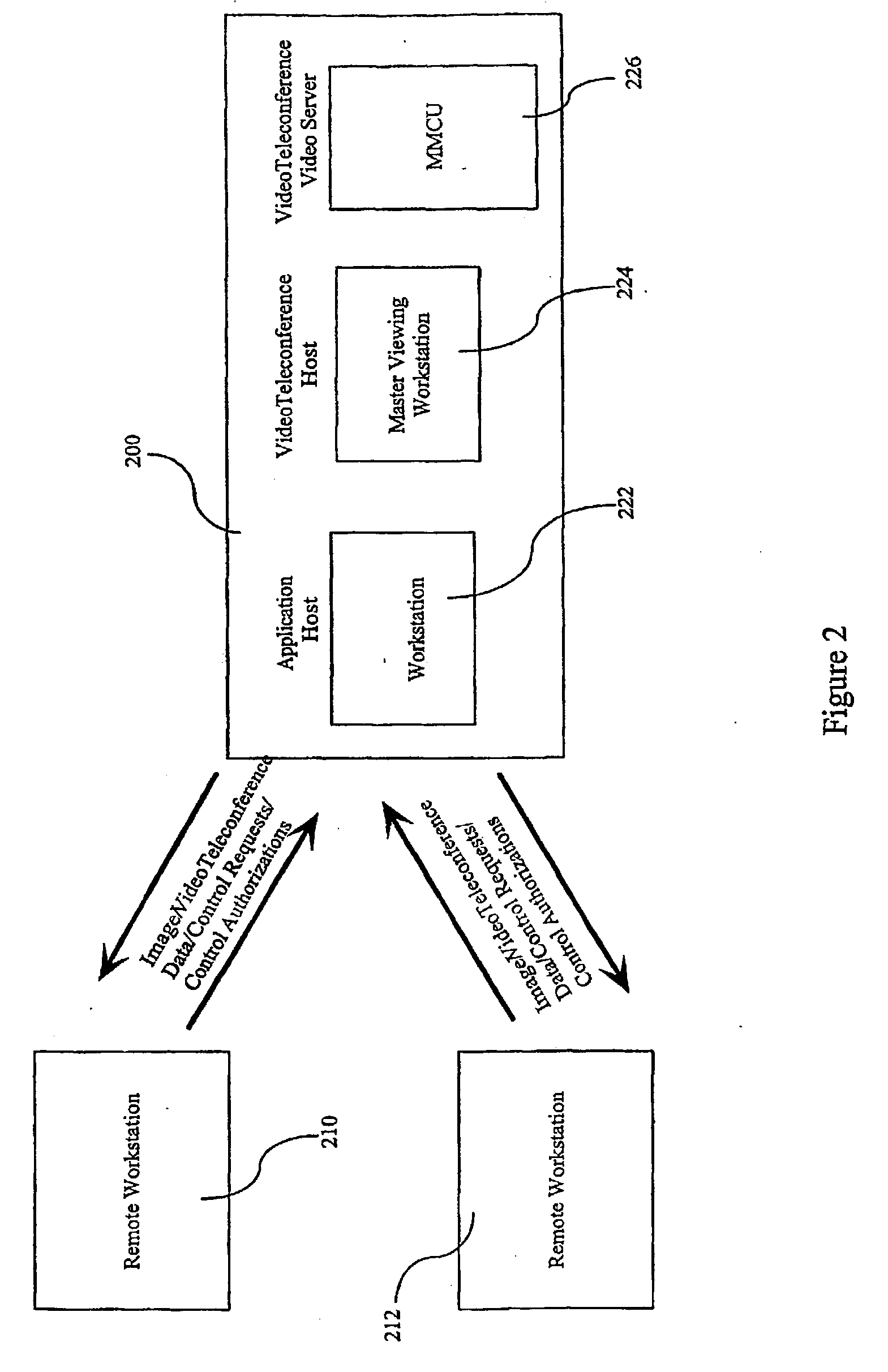
[0015] FIG. 1 illustrates an example of a typical hardware configuration on which the method of the present invention may be practiced. It is understood that the present invention is not limited to this configuration and the components described herein; they are provided by way of example to help explain the method of the present invention and an environment in which it could operate.

[0016] For the purpose of this example, the term "treatment planning site" refers to a main medical facility, such as The Johns Hopkins Hospital Oncology Center in Baltimore, Md., and the term "care delivery site" refers to a remote location where the medical treatment defined in the treatment plan would be delivered, such as, for example, The Johns Hopkins Green Spring Clinic in Lutherville, Md. or the Peninsula Regional Medical Center in Salisbury, Md. It is understood that it is not necessary that the treatment planning site and the care delivery site be at different locations.

[0017] Referring to FI...


PUM


Abstract

A medical treatment planning system which enables multiple collaborators in different locations to interactively view and manipulate data for use in, for example, preparing a treatment plan while also interacting with each other. Interactive medical treatment planning involving multiple participants using multiple treatment planning stations includes establishing one of the treatment planning stations as a session controller and launching treatment planning software thereon; establishing a communication connection between the session controller planning station and all of the treatment planning stations participating in a planning session; and displaying, on all participating treatment planning stations, treatment plan information being displayed on the session controller treatment planning station. The system also designates one of the treatment planning stations as an active controller for controlling manipulation of the treatment planning information, which may be regulated by the session controller treatment planning station.

Description

[0001] This application claims the benefit of prior-filed U.S. Provisional Application No. 60 / 187,521, filed on Mar. 7, 2000.[0002] 1. Field of the Invention[0003] The present invention relates to a method and system for medical treatment planning and more particularly to a method and system for medical treatment planning involving interactive communication between medical personnel at diverse locations, and real-time viewing and manipulation of the same data by all parties utilizing the system.[0004] 2. Description of the Prior Art[0005] Traditionally, when a patient needed medical consultation and / or treatment, the patient had to travel to the location of the medical professional(s) providing the diagnostic, planning, and treatment services. Complex medical treatments (e.g., radiation therapy) typically involve a collaborative effort between various members of one or more departments within a medical institution. For example, with respect to radiation therapy, within a Radiation O...

Claims


Application Information

Patent Timeline
IPC IPC(8): G06F19/00G06Q10/10G06Q50/22
CPCG06F19/3418G06F19/3425G06Q50/22G06Q10/10G06F19/3481G16H80/00G16H20/40G16H40/67
Inventor LOMBARDO, JOSEPH S.WOJCIK, RICHARD A.LOSCHEN, WAYNE A.WHITE, DAVID M.DICELLO, JOHN F.MYERS, LEE T.GAUDETTE, RAYMOND
Owner THE JOHN HOPKINS UNIV SCHOOL OF MEDICINE
Learn More