
Cooling system for a motor vehicle comprising a closing unit for the cooling airflow

a technology for cooling systems and motor vehicles, which is applied in the direction of electric control, machines/engines, transportation and packaging, etc., can solve the problems of engine damage, control of cooling performance, and inability to ensure the opening angle of the predetermined angl

Inactive Publication Date: 2003-06-05
ROBERT BOSCH GMBH
View PDF0 Cites 19 Cited by
  • Summary
  • Abstract
  • Description
  • Claims
  • Application Information

AI Technical Summary

Benefits of technology

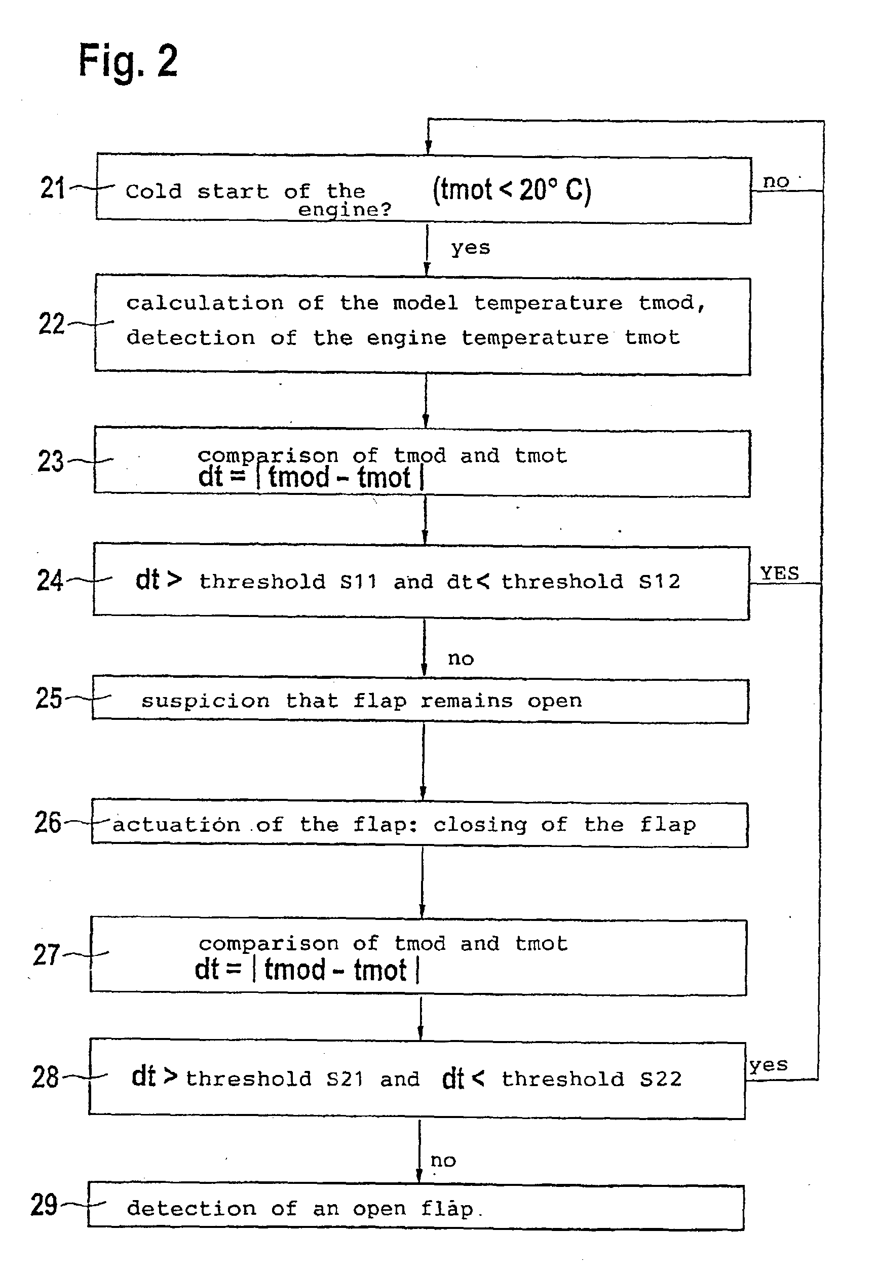
[0004] The cooling system of a motor vehicle according to the invention, with a closure unit for the cooling air stream, which has the characterizing features of the main claim, has the advantage over the prior art that a misadjustment of the closure unit is detected by means of the temperature progression. In this connection, it is particularly advantageous that no additional sensor is required for detecting the opening angle of the closure unit. This reduces costs.[0005] Advantageous modifications and improvements of the cooling system disclosed in the main claim are possible by means of the measures taken in the dependent claims. It is particularly advantageous that a tolerance range is provided for the progression of a model temperature so that then, by means of a simple comparison to the actual temperature, a temperature difference is detected and the cause can be sought. If the closure unit is opened, for example, although the engine temperature is too low, then it can be concluded from this that the opening angle for the closure unit is too great. On the other hand, if the engine temperature is too high, then it can be assumed that the closure unit is closed so that the cooling air stream is insufficient.[0006] If a misadjustment of the closure unit is suspected based on the above criteria, then in order to support this thesis by means of an intentional adjustment of the opening angle of the closure unit and control of the corresponding temperature progression, a test can once again be made as to whether the suspected cause lay in the adjustment of the opening angle of the closure unit. For the sake of simplicity, this is possible with a second tolerance range, for which a corresponding model progression is stored, so that the suspected misadjustment can be checked by means of a simple plausibility test.[0007] The model progression for the cooling water temperature is advantageously determined empirically for a particular motor vehicle type or engine type so that this model is supported by the results of actual practice.[0008] It is also favorable to store the model progression, along with its parameters, in a nonvolatile memory so that they are available even after a power failure.[0009] It has also turned out to be favorable to select a closure unit for storage, which is produced, for example, from a butterfly valve or a louver. These parts are easy to manufacture and can be controlled, for example, with small electric motors.

Problems solved by technology

With the known cooling system, however, there is the problem that the desired control of the cooling performance depends on the functional reliability of the closure unit, i.e. in particular of the ventilation flap.
If the ventilation flap is jammed, which can occur, for example, in winter due to freezing or being coated by snow or ice, then it cannot be assured of reaching its predetermined opening angle.
In the extreme case, this can cause the engine to overheat and as a result, lead to engine damage.

Method used


Image

  • Cooling system for a motor vehicle comprising a closing unit for the cooling airflow
  • Cooling system for a motor vehicle comprising a closing unit for the cooling airflow
  • Cooling system for a motor vehicle comprising a closing unit for the cooling airflow

Examples


Embodiment Construction

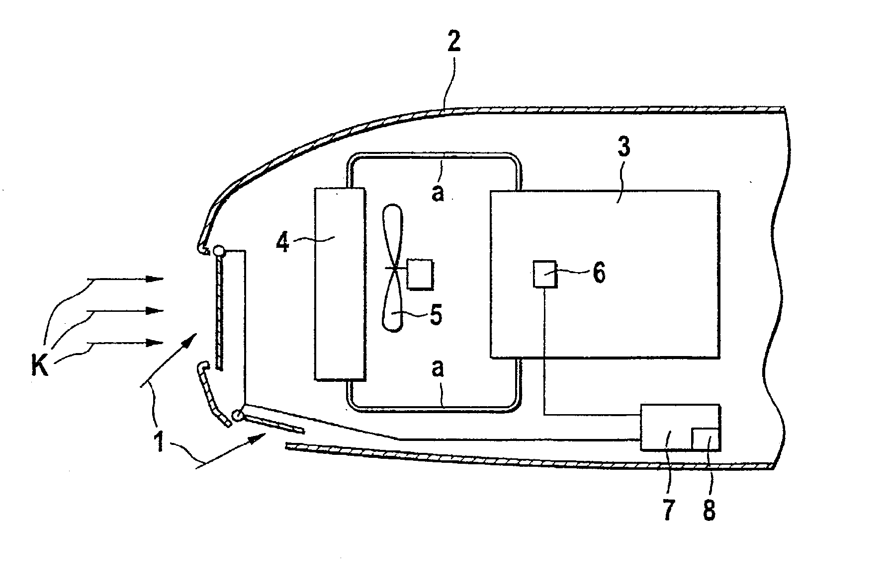
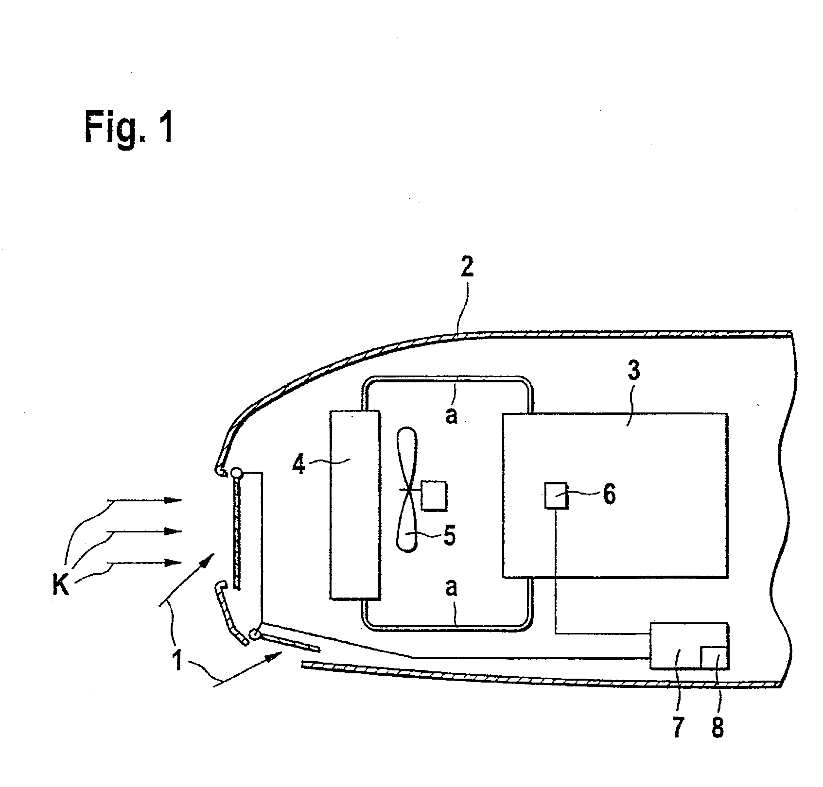
[0014] FIG. 1 schematically depicts an engine compartment 2, which is essentially completely encapsulated and has openings for the cooling air flow K oriented in the travel direction. The openings are embodied with suitable closure units 1, for example flaps or louvers. At least one radiator 4 is situated in the engine compartment 2, with a correspondingly provided fan 5 that draws the cooling air stream K through the radiator 4 and consequently dissipates the stored heat from the radiator 4. By means of openings that are not shown, the heated air stream is conveyed either into the open air or is optionally used to heat the passenger compartment of the motor vehicle. There is also an engine 3 embodied as an internal combustion engine, which has at least one sensor 6 for measuring the temperature of the cooling water. The engine 3 is connected to the radiator 4 via suitable radiator hoses. The required valves, pumps, etc. have been omitted for the sake of visibility.

[0015] A control ...


PUM


Abstract

The invention proposes a cooling system of a motor vehicle, in which a closure unit for the cooling air stream, in order to optimize the operating parameters of the internal combustion engine, is monitored as to its function. This closure unit, preferably a flap or louver for controlling the cooling air stream, is monitored as to its function in order to prevent a temperature buildup or a failure to reach the operating temperature. In order to monitor the position of the closure unit (1), the invention therefore proposes using a temperature sensor that is as a rule present, to compare the progression of the cooling water temperature to a stored model progression of the temperature. If the cooling water temperature lies within a predetermined tolerance range, then the closure unit is functioning properly. Otherwise, it is assumed that the closure unit is jammed. In this instance, the closure unit is intentionally actuated and the subsequent temperature progression is compared to a stored model progression. If the cooling water temperature now lies outside another predetermined tolerance range (S21, S22), then this is an indication that the closure unit (1) is jammed. This problem is indicated and / or stored.

Description

PRIOR ART[0001] The invention is based on a cooling system for a motor vehicle, with a closure unit for the cooling air stream in order to optimize the operating parameters of the internal combustion engine, as generically defined by the preamble to the main claim. JP-100 77 838 A has already disclosed a control unit with which the opening angle and / or closing angle of a ventilation flap for the radiator is controlled as a function of the engine temperature. In this connection, a temperature sensor detects the cooling water temperature of the engine and a first computer calculates the time-dependent progression of the temperature change. Based on this, a second computer determines the opening angle to be set for the ventilation flap.[0002] WO 890 44 19 A has disclosed a cooling system for the engine of a motor vehicle in which in addition to the mechanically driven coolant pump, an electrically driven coolant pump can be switched on as a function of the operating parameters. By mean...

Claims


Application Information

Patent Timeline
Patent Type & Authority Applications(United States)
IPC IPC(8): B60K11/04F01P7/02F01P7/12F01P11/16F01P11/20F02D45/00
CPCF01P7/026F01P7/12F01P2031/00F01P11/20F01P2023/00F01P11/16
Inventor RIES-MUELLER, KLAUS
Owner ROBERT BOSCH GMBH
Learn More