
Adjustable tip for a lancet device and method

a technology of adjustable tip and lancet, which is applied in the field of lancet, can solve the problems that many users simply cannot perform the procedure, the procedure is often problematic for the user, and the control of the depth of penetration cannot be reliably accomplished withou

Inactive Publication Date: 2003-05-08
STAT MEDICAL DEVICES
View PDF92 Cites 63 Cited by
  • Summary
  • Abstract
  • Description
  • Claims
  • Application Information

AI Technical Summary

Benefits of technology

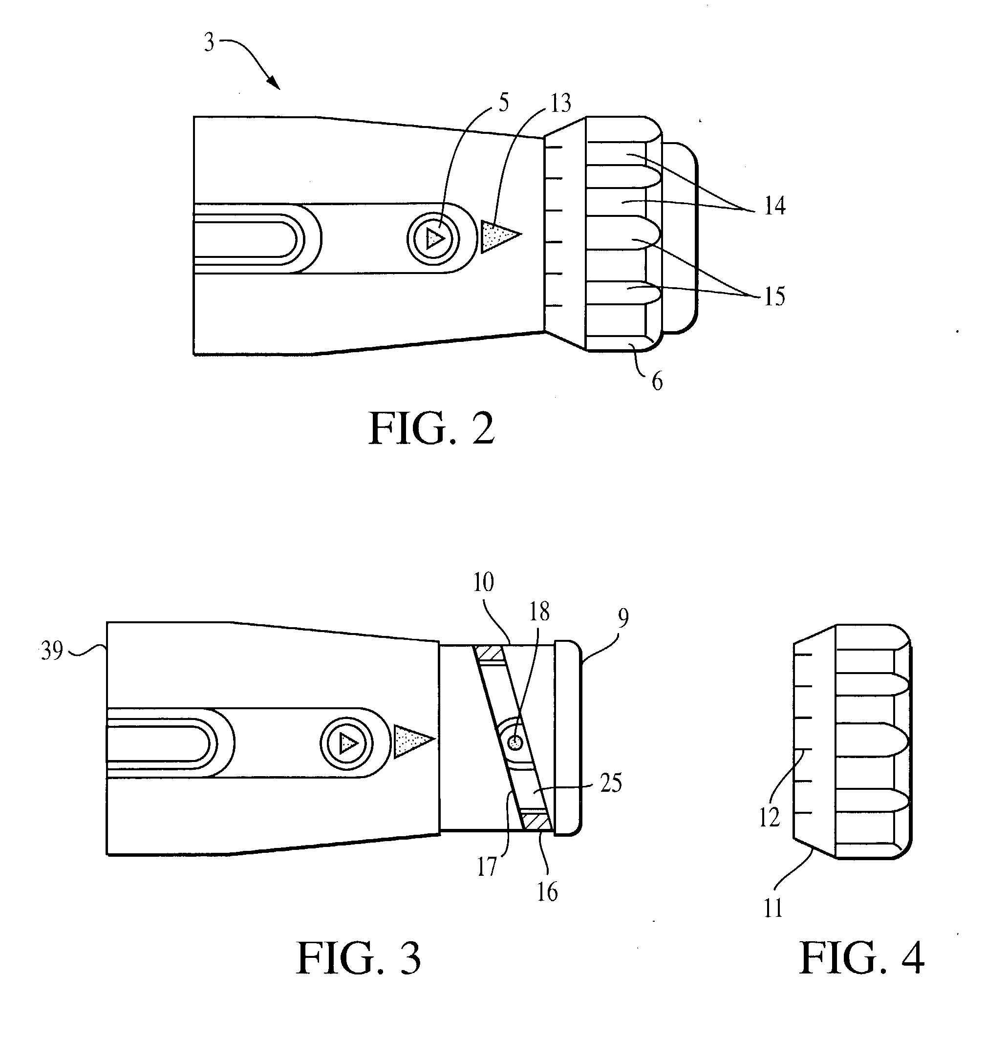
[0026] The stop cap also has a camming lug which travels in a camming slot formed in a side wall of the front cap. The lug projects through the camming slot and further into a recess formed on an inside surface of the nut. In operation, this design allows the stop cap to rotate as well as move forwards and backwards, based upon rotational movement of the nut. The camming slot in the front cap is angled in such a way to allow the stop cap to be precisely positioned within the front cap. The stop cap functions, as its name suggests, as a stop for the lancet. That is, it acts to stop the movement of the lancet after it is fired in the direction of the tip. For this purpose, the stop cap has a stop surface which prevents the lancet from moving any further past a set point. Moreover, the stop cap includes a through hole which allows the needle to protrude therethrough. As a result of the needle being fixed to the lancet, the stop cap also prevents the needle's movement past a set point.
[0029] In one particular embodiment of the device, the nut is located on the front cap and sits back some distance from a distal surface. The distal surface being a surface which contacts the skin of the user and through which the needle projects. One advantage of this embodiment is that the nut may be easier to fabricate.
[0030] In another embodiment of the device, the nut itself includes the distal surface with the corresponding distal opening. One advantage of this embodiment is that the nut has a longer axial length which can be easier to grip. Another advantage is that the front cap may be easier to fabricate owing to its cylindrical shape having both ends open.
[0032] As explained above in connection with the device, the method allows the user to extract one of more drops of blood more efficiently, precisely, consistently, and with less discomfort to the user.

Problems solved by technology

However, this procedure is often problematic for the user since the needle may be difficult to handle.
Moreover, controlling the depth of penetration cannot be reliably accomplished without the use of a mechanical device.
Additionally, many users simply cannot perform the procedure owing to either a fear of needles or because they lack a steady hand.
Presently, most lancet devices lack convenient and flexible adjustability.
This, of course, creates the problem of storing the replaceable tips, which if not properly done, may result in their misplacement, damage, contamination, or the like.
The SLAMA device is characterized as a "single bottom" device which employs a threaded design which can be expensive to manufacture.
Further, such a threaded resign is prone to inadvertent setting changes since there is nothing but frictional engagement between the mating threads to maintain the adjustment setting.
However, the lancet and needle will not be allowed to travel past a stop point determined by the stop cap.
However, should an insufficient amount of blood not surface from the puncture, the device can be re-adjusted to allow the needle to penetrate still a little further into the skin.

Method used


Image

  • Adjustable tip for a lancet device and method
  • Adjustable tip for a lancet device and method
  • Adjustable tip for a lancet device and method

Examples


Embodiment Construction

[0074] The particulars shown herein are by way of example and for purposes of illustrative discussion of the embodiments of the present invention only and are presented in the cause of providing what is believed to be the most useful and readily understood description of the principles and conceptual aspects of the present invention. In this regard, no attempt is made to show structural details of the present invention in more detail than is necessary for the fundamental understanding of the present invention, the description taken with the drawings making apparent to those skilled in the art how the several forms of the present invention may be embodied in practice.

[0075] FIG. 1 shows one embodiment of lancet device 1. Lancet device 1 has a lancet body portion 2 and a front assembly or front cap mechanism 3 (also referenced herein as a tip or front portion). In one particular embodiment lancet device 1 includes a rear trigger mechanism 8 in the form of a push button. The details of...


PUM


Abstract

A lancet device and a lancet device tip for a lancet device. The tip includes a first sleeve and a second sleeve at least partially contained within the first sleeve. The second sleeve includes a stop surface. Rotation of the first sleeve relative to the second sleeve causes the second sleeve to move at least axially without changing an overall length of the lancet device tip.

Description

[0001] The present application is a continuation of U.S. Application Ser. No. 09 / 493,675 filed Jan. 28, 2000, the disclosure of which is expressly incorporated by reference herein in its entirety.[0002] 1. Field of the Invention[0003] The invention relates to a lancet device, an adjusting front mechanism for use on a lancet device, and a method of using a lancet device. In particular, the invention includes a lancet device which utilizes an adjustable tip or front. Lancet devices are used to penetrate and puncture the skin in order to allow the taking of a blood sample for testing. The device allows the user to control the depth of this penetration by a simple adjustment mechanism.[0004] 2. Discussion of Background Information[0005] Lancet devices are commonly used to prick the skin of the user so that one or more drops of blood may be extracted for testing. Some users such as diabetics, for example, may have to test their blood sugar levels several times a day. This may be accompli...

Claims


Application Information

Patent Timeline
Patent Type & Authority Applications(United States)
IPC IPC(8): A61B5/15A61B17/32A61M3/00
CPCA61M3/00A61B5/15186A61B5/15107A61B5/1411
Inventor SCHRAGA, STEVEN
Owner STAT MEDICAL DEVICES
Learn More