
Amplitude-offset invariant template detection for pulse position estimation; methods, systems & program products

a template detection and pulse position technology, applied in the field of pulse position detection systems, methods, system and program products, can solve the problems of not meeting the particular stringent accuracy requirements necessary, poor accuracy in analyzing vertically shifted signals, and suspect accuracy of many pulse-position detection systems, etc., to remove or minimize any signal offset or modulation

Inactive Publication Date: 2003-05-08
SYMBOL TECH INC
View PDF16 Cites 9 Cited by
  • Summary
  • Abstract
  • Description
  • Claims
  • Application Information

AI Technical Summary

Benefits of technology

[0017] Another aspect removes or minimizes any signal offsets or modulations present in the signal prior to position estimation.

Problems solved by technology

The accuracy of many pulse-position detection systems, however, becomes suspect in the presence of noise corruption and multipath impairments (the random combination of multiple, time-shifted versions of the signal).
1 This technique, though robust against noise corruption and multipath, suffers from poor accuracy in analyzing vertically shifted signals (shifts with respect to the amplitude axis, not time).
Similarly, none of the prior art provides solutions meeting the particularly stringent accuracy requirements necessary for real-time location tracking in the IEEE 802.11 local-area-network signal environment.

Method used


Image

  • Amplitude-offset invariant template detection for pulse position estimation; methods, systems & program products
  • Amplitude-offset invariant template detection for pulse position estimation; methods, systems & program products
  • Amplitude-offset invariant template detection for pulse position estimation; methods, systems & program products

Examples


Embodiment Construction

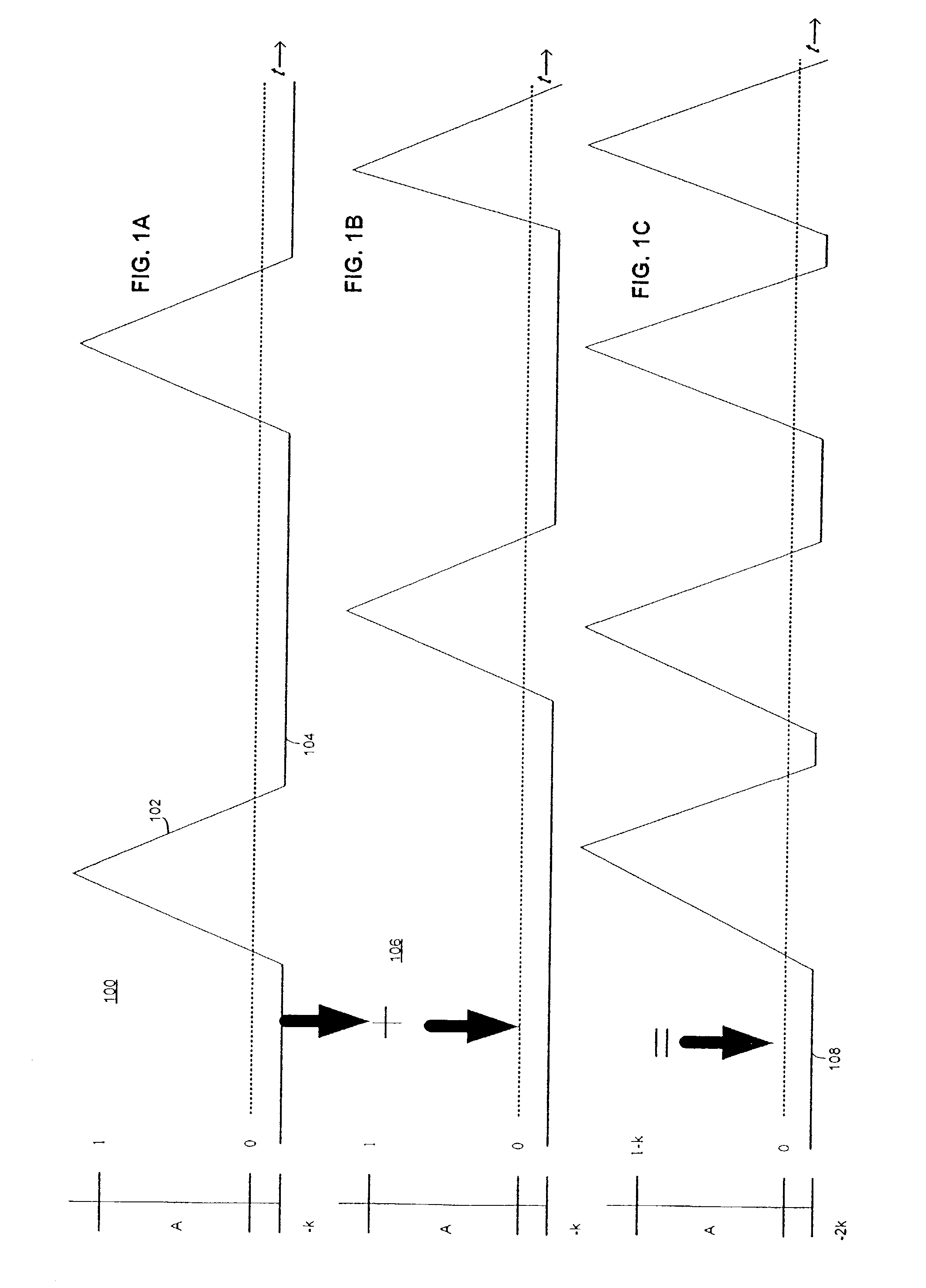
[0044] Assume that a single predetermined shape or "peak" is contained in the discrete sequence, p(n), which is modulated by the channel and amplitude offset by the effects of multipath. (We do not incorporate noise at this time.) The received signal, s(n), for the length of one bit period, T, may therefore be defined below in equation 1:

{haeck over (s)}(n)=A.p(n)+B;0.ltoreq.n.ltoreq.T

[0045] Where:

[0046] A=Signal Modulation Constant

[0047] B=Signal Amplitude Offset

[0048] p=Received Signal Peak

[0049] n=Time, in samples

[0050] T=Single Bit Period, in samples

[0051] A and B are arbitrary constants representing modulation and an amplitude offset, respectively. It is necessary to compensate for A and B so that the position of p(n) may be determined accurately.

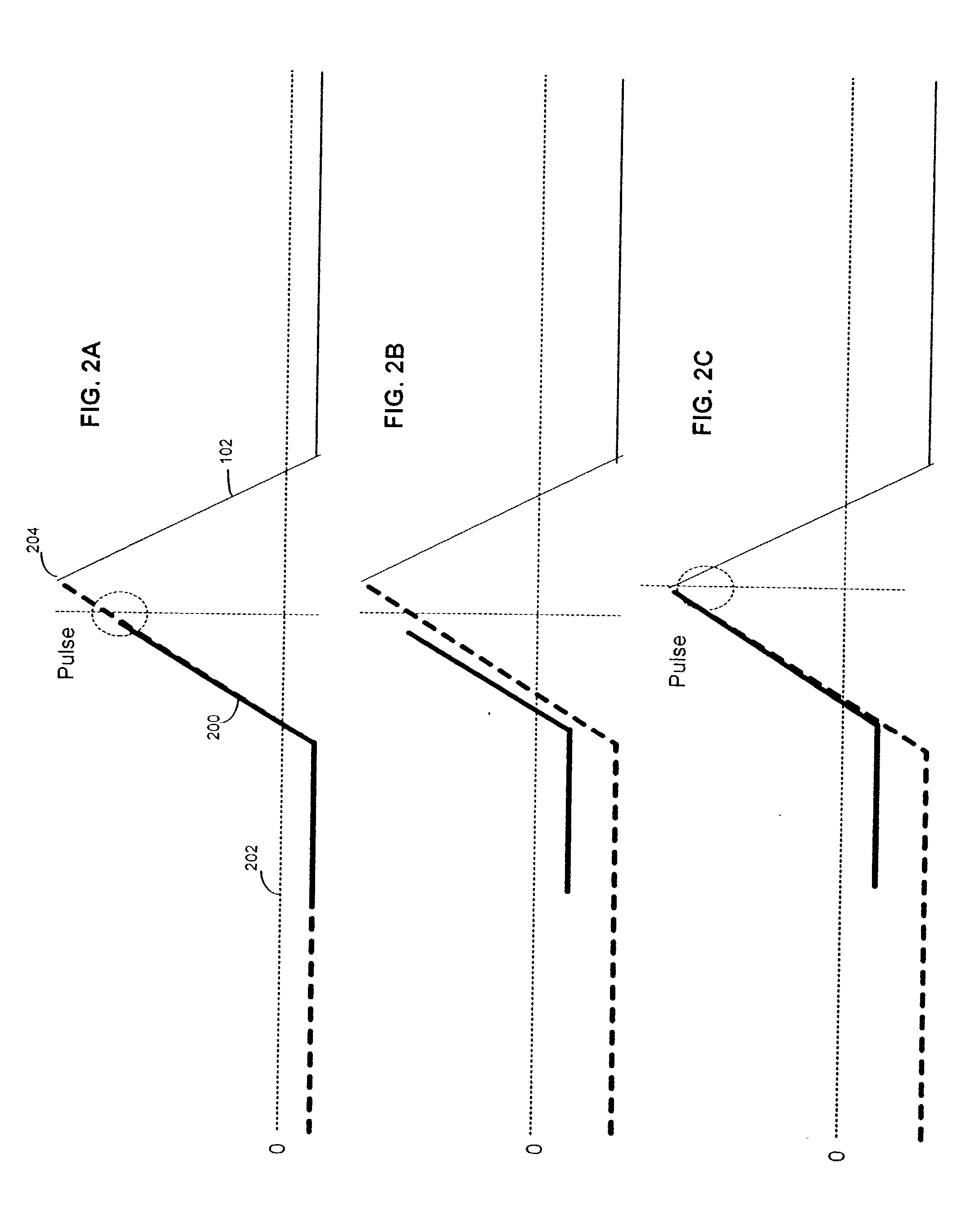
[0052] Further assume that the template is k samples shorter than p(n). Rather than the full "peak", the template represents the "leading edge" of the "peak". Therefore, the template of length T-k=N, is defined below in equation 2 as:

{...


PUM


Abstract

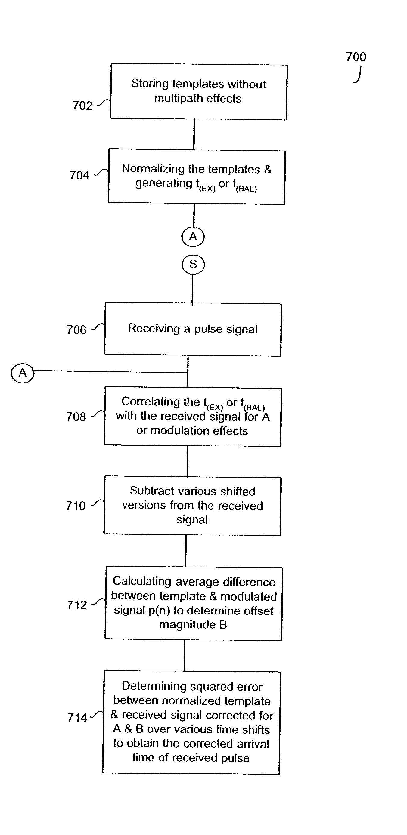
A method of determining and correcting for modulation and offset effects in a received signal. A signal [s(n)] is received subject to modulation effects A on pulse shape or peak [p(n)] and vertical offset B due to multipath where "n" is a pulse rate or samples of the signal. A template of length N incorporates a replica of the original signal [s(n)] without multipath or vertical offset. The template is normalized and generates either an extended template or a balanced template. The extended template is correlated with the received signal [s(n)] by shifting the extended template along the received signal to estimate modulation effects of A at a particular time, n. Various sample shifted versions of the template are subtracted from the modulation-compensated (using the estimate of A for the particular time, n) received signal. The average difference between the template and the modulated signal [p(n)] is calculated to determine the magnitude of the offset B for a particular time, n. The squared error is determined between the normalized and the corrected template (A, B) for the received signal.

Description

[0001] This application claims the benefit of the filing date of Provisional Application No. 60 / 346,713, filed Oct. 25, 2002, assigned by the same assignee as that of the present invention and fully incorporated herein by reference.BACKGROUND OF INVENTION[0002] 1. Field of Invention[0003] This invention relates to pulse position detection systems, methods and program products. More particularly, the invention relates to amplitude-offset invariant template detection for pulse position estimation: methods, systems and program products.[0004] 2. Description of Prior Art[0005] The operation of many discrete systems is based on analysis of a signal in order to find the existence and position (in time) of a predetermined shape. Laser-scanner decoding, mobile ranging, and digital signal processing for feature extraction all depend on knowledge of the position of particular shapes within a signal, not merely their existence. This type of positional analysis is useful in any application wher...

Claims


Application Information

Patent Timeline
Patent Type & Authority Applications(United States)
IPC IPC(8): H04L25/03
CPCH04L25/03006H04B1/7075
Inventor HERNANDEZ, DAVIDGOREN, DAVID
Owner SYMBOL TECH INC
Learn More