
Method and device for inspecting laminated iron cores of electrical machines for interlamination shorts

a laminated iron and electrical machine technology, applied in the direction of magnetic property measurement, material magnetic variables, instruments, etc., can solve the problems of not being able to draw any reliable conclusion with regard to the volt-amperes flowing in the fault point, and the temperature increase on its own is not sufficient for quantitative assessment of the interlamination short poin

Inactive Publication Date: 2003-03-27
GENERAL ELECTRIC TECH GMBH
View PDF1 Cites 16 Cited by
  • Summary
  • Abstract
  • Description
  • Claims
  • Application Information

AI Technical Summary

Benefits of technology

[0013] Another preferred embodiment is characterized in that the induced electrical signals are compared with signals which correspond to the interlamination short currents, with a loop with an appropriate width being mounted on the surface of the laminated iron core as a reference for this purpose, and being fed with an appropriate interlamination short current. This method allows quantification of the fault points, that is to say, in particular, it allows determination of the volt-amperes which effectively flow in a fault point. It is thus possible to detect the actual fault points with reference to any possible "core melting".
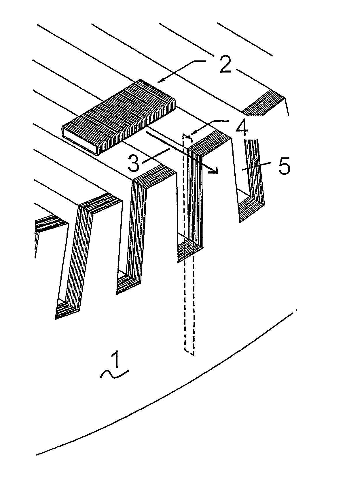
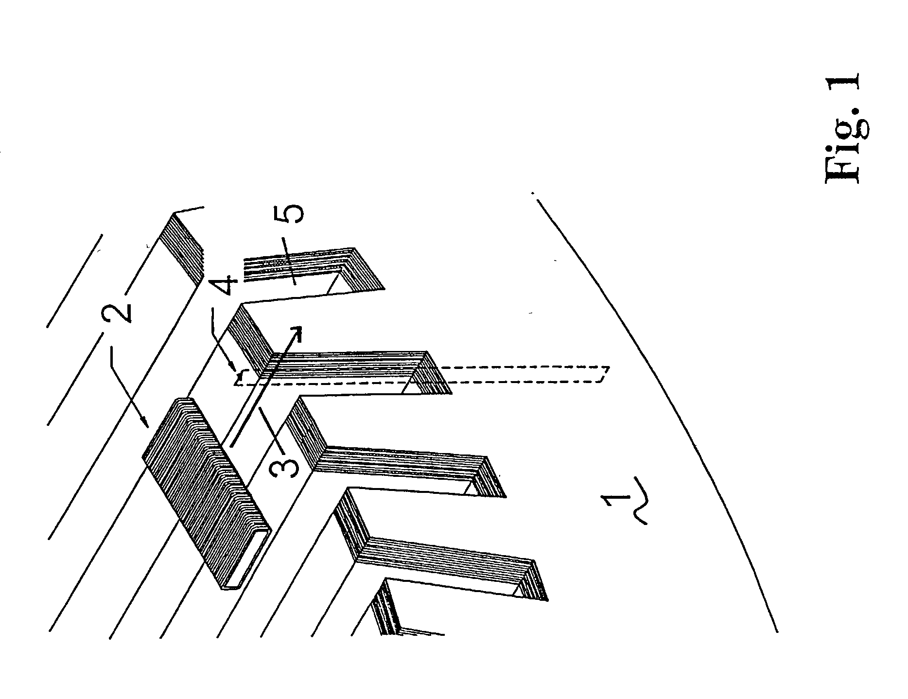
[0016] Furthermore, the present invention relates to an apparatus for carrying out a method as described above, comprising first means for determining the position of the measurement coil arrangement on the laminated iron core, comprising second means for detecting the amplitude and the phase, in particular by means of a phase detector, of the electrical voltage which is induced in the measurement coil arrangement, and also comprising a data processing unit, which analyzes the measured data and, in particular, is able to localize critical interlamination shorts and to determine the volt-amperes flowing in them, by comparison with a reference. Normally, the position of the measurement coil arrangement can in this case be detected using the first means, and the measured value can be detected using the second means. This information is supplied to the data processing system, thus making it possible to obtain an overall image of the state of the stator. The first means may in this case be designed, for example, in the form of a measurement unit relating to the movement position of a robot carriage to which the measurement coil arrangement or arrangements is or are fitted.

Problems solved by technology

The temperature increase on its own is not sufficient for quantitative assessment of the interlamination short point.
U.S. Pat. No. 5,321,362 is in this case based exclusively on a current measurement, and therefore does not make it possible to draw any reliable conclusion with regard to the volt-amperes flowing in the fault point.
One fundamental problem in the context of such low-induction methods is the fact that they frequently do not allow unique localization of fault points, since differences in the behavior of the magnetic iron core (for example resulting from cooling slots) can also lead to signals which, with these methods, may possibly also be interpreted as fault points.

Method used


Image

  • Method and device for inspecting laminated iron cores of electrical machines for interlamination shorts
  • Method and device for inspecting laminated iron cores of electrical machines for interlamination shorts
  • Method and device for inspecting laminated iron cores of electrical machines for interlamination shorts

Examples


Embodiment Construction

[0007] One object of the present invention is therefore to propose a method for inspecting laminated iron cores of electrical machines for interlamination shorts, in which method the laminated iron core is magnetized by means of an auxiliary winding and the iron surface is scanned by means of at least one measurement coil arrangement with a downstream measurement device, and which allows fault points, that is to say any interlamination shorts which may be present, to be localized as uniquely as possible.

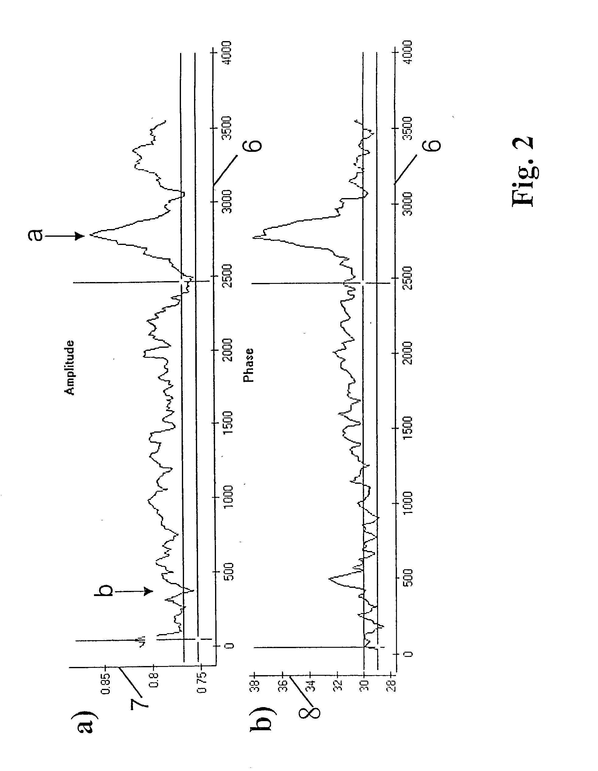
[0008] The object is achieved in that both the phase and the amplitude of the electrical signal which is induced in the at least one measurement coil arrangement are used in combined form to localize interlamination shorts. Thus, in contrast to the methods according to the prior art, not only the amplitude or not only the phase is used to localize the interlamination shorts, but the phase and amplitude information is used in a combined manner to identify them.

[0009] This is because, ...


PUM

PropertyMeasurementUnit
voltageaaaaaaaaaa
voltageaaaaaaaaaa
poweraaaaaaaaaa

Abstract

The present invention relates to a method, an apparatus and a computer program for inspecting laminated iron cores (1) of electrical machines for interlamination shorts, in which the laminated iron core (1) is magnetized by means of an auxiliary winding, and the iron surface is scanned by means of at least one measurement coil arrangement (2) with a downstream measurement device. In this case, unique and quantifiable localization of interlamination shorts is achieved by using both the phase (8) and the amplitude (7) of the electrical signal which is induced in the at least one measurement coil arrangement (2), in combined form.

Description

[0001] The invention relates to a method for inspecting laminated iron cores of electrical machines for interlamination shorts, in which the laminated iron core is magnetized by means of an auxiliary winding and the iron surface is scanned by means of a measurement coil arrangement with a downstream measurement device.[0002] The invention also relates to an apparatus for carrying out the method, and to a computer program for data evaluation.PRIOR ART[0003] Laminated iron cores, in particular of electrical machines, are frequently inspected for interlamination shorts during production and in the course of maintenance work during operation, using the measurement method of stator laminate ring excitation with rated induction. This method which indicates the effect of interlamination short currents in the form of local temperature differences, demands a powerful voltage source which can be regulated, and field windings with large cross sections (so-called hot spot method using, for exam...

Claims


Application Information

Patent Timeline
Patent Type & Authority Applications(United States)
IPC IPC(8): G01N27/90G01R31/34
CPCG01N27/9046G01R31/34
Inventor HOBELSBERGER, MAXKIRCHHOFF, INGONODWELL, ERICPOSEDEL, ZLATIMIR
Owner GENERAL ELECTRIC TECH GMBH
Learn More