
Power supply system and power supply method

a power supply system and power supply technology, applied in the direction of motor/generator/converter stopper, electric device, propulsion parts, etc., can solve the problems of large loss in the motor and the inverter driving the motor, and the power consumption of comparatively low resistances such as the internal resistance of the battery and wiring cannot be ignored

Inactive Publication Date: 2003-03-27
TOYOTA JIDOSHA KK
View PDF6 Cites 43 Cited by
  • Summary
  • Abstract
  • Description
  • Claims
  • Application Information

AI Technical Summary

Problems solved by technology

Some of these types of vehicle mounted electrical components have comparatively large power consumption, such as motors such as starter motors, air conditioner motors, power steering motors etc., or various heaters.
With large power devices, if the source voltage is low, then a large current must flow to obtain large amounts of power, but the power consumed by comparatively low resistances such as the internal resistance of the battery and wiring can not be ignored, and there is also a large amount of loss in the motor and an inverter driving the motor.
It is also possible to provide two generators respectively corresponding to each power supply, but it is difficult to keep the cost of a system having two generators down.
However, by providing the dedicated DCDC converter circuit, the overall cost of the dual power supply system is increased significantly.

Method used


Image

  • Power supply system and power supply method
  • Power supply system and power supply method
  • Power supply system and power supply method

Examples


Embodiment Construction

[0048] Embodiments of the present invention will be described below based on the drawings.

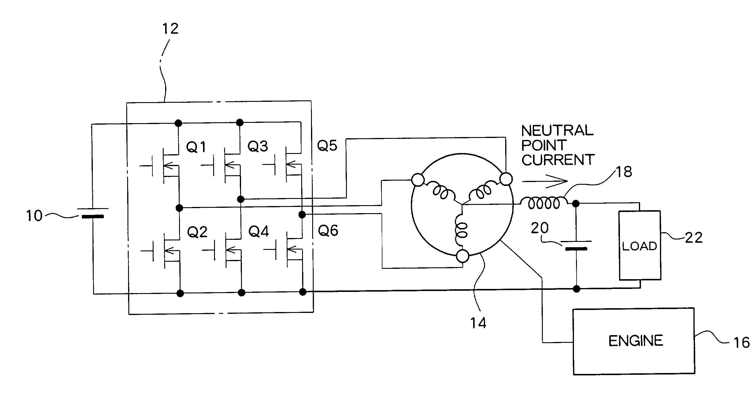
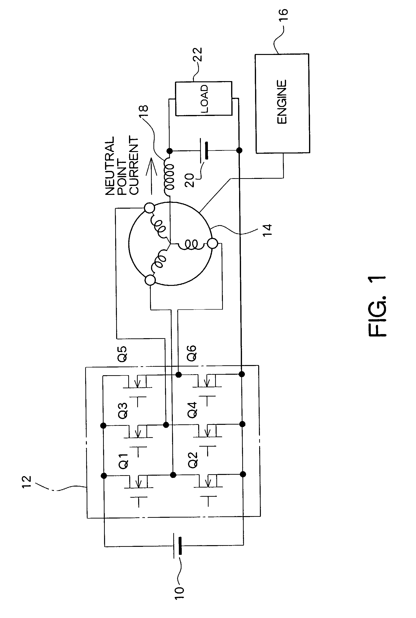
[0049] FIG. 1 is a drawing showing the structure of a first embodiment, in which both ends of a high voltage (36V) battery 10 are connected to an inverter 12. A negative electrode of the high voltage battery 10 is connected to earth, such as the vehicle body, while the positive electrode constitutes a power source line. Secondary batteries such as nickel hydrogen or lithium ion batteries are used in the high voltage battery 10.

[0050] The inverter 12 is made up of six switch elements (N-channel transistors). Specifically, a U phase arm constituted by transistors Q1 and Q2 connected in series, a V phase arm constituted by transistors Q3 and Q4 connected in series, and a W phase arm constituted by transistors Q5 and Q6 connected in series is arranged between the power source line and earth. Intermediate points of each phase arm of the inverter 12 are connected to respective ends of respective phas...


PUM


Abstract

Power from a high voltage battery (10) (for example 36V) is supplied through an inverter (12) to a motor generator (14). A low voltage battery (20) (for example 12V) is connected through a reactor (18) to the neutral point of the motor generator (14). A voltage ratio of the low voltage battery (20) to the high voltage battery (10) is preferably from 1:2 to 1:4. In order to set the neutral point voltage to a desired charging voltage into the low voltage battery (20), the inverter (12) is controlled so as to follow a current distortion phenomenon. In this way, in a dual-power source system with a voltage ratio of a low voltage battery (20) to a high voltage battery (10) between 1:2 and 1:4, voltage switching means for use in charging a charge voltage of a high voltage side into a low voltage source can be implemented at low cost.

Description

[0001] 1. Field Of The Invention[0002] The present invention relates to a power supply system, provided with a current supply system having a high voltage system and a low voltage system, for driving a motor with power from the high voltage system.[0003] 2. Description of the Related Art[0004] Conventionally, internal combustion engines (engines) using fuel such as gasoline have been widely used as a source of power for vehicles. Various types of device are installed in this type of vehicle, and a lot of these devices are driven by electrical power. Vehicles are therefore fitted with a battery, and various electrical devices mounted in the vehicle are powered by electrical power from this battery.[0005] Some of these types of vehicle mounted electrical components have comparatively large power consumption, such as motors such as starter motors, air conditioner motors, power steering motors etc., or various heaters. Electrical power of electrical devices is determined by multiplying ...

Claims


Application Information

Patent Timeline
IPC IPC(8): H02J7/14B60K6/20B60K6/22B60K6/26B60K6/28B60K6/485B60L11/18B60W10/08B60W20/00H02M7/5387
CPCB60K6/48B60L11/1868Y02T10/6221Y02T10/7005Y02T10/7066Y10S903/906Y10S903/907Y10S903/904B60L1/00B60L3/003B60L3/04B60L2210/40B60L2240/421B60L2240/547B60L2240/549Y02T10/7241Y02T10/642B60L58/20Y02T10/62Y02T10/64Y02T10/70Y02T10/72H02J2310/48
Inventor KUSAKA, YASUSHITSUJI, KIMITOSHI
Owner TOYOTA JIDOSHA KK
Learn More