
Coding scheme for a wireless communication system

Inactive Publication Date: 2003-03-06
QUALCOMM INC
View PDF12 Cites 386 Cited by
  • Summary
  • Abstract
  • Description
  • Claims
  • Application Information

AI Technical Summary

Benefits of technology

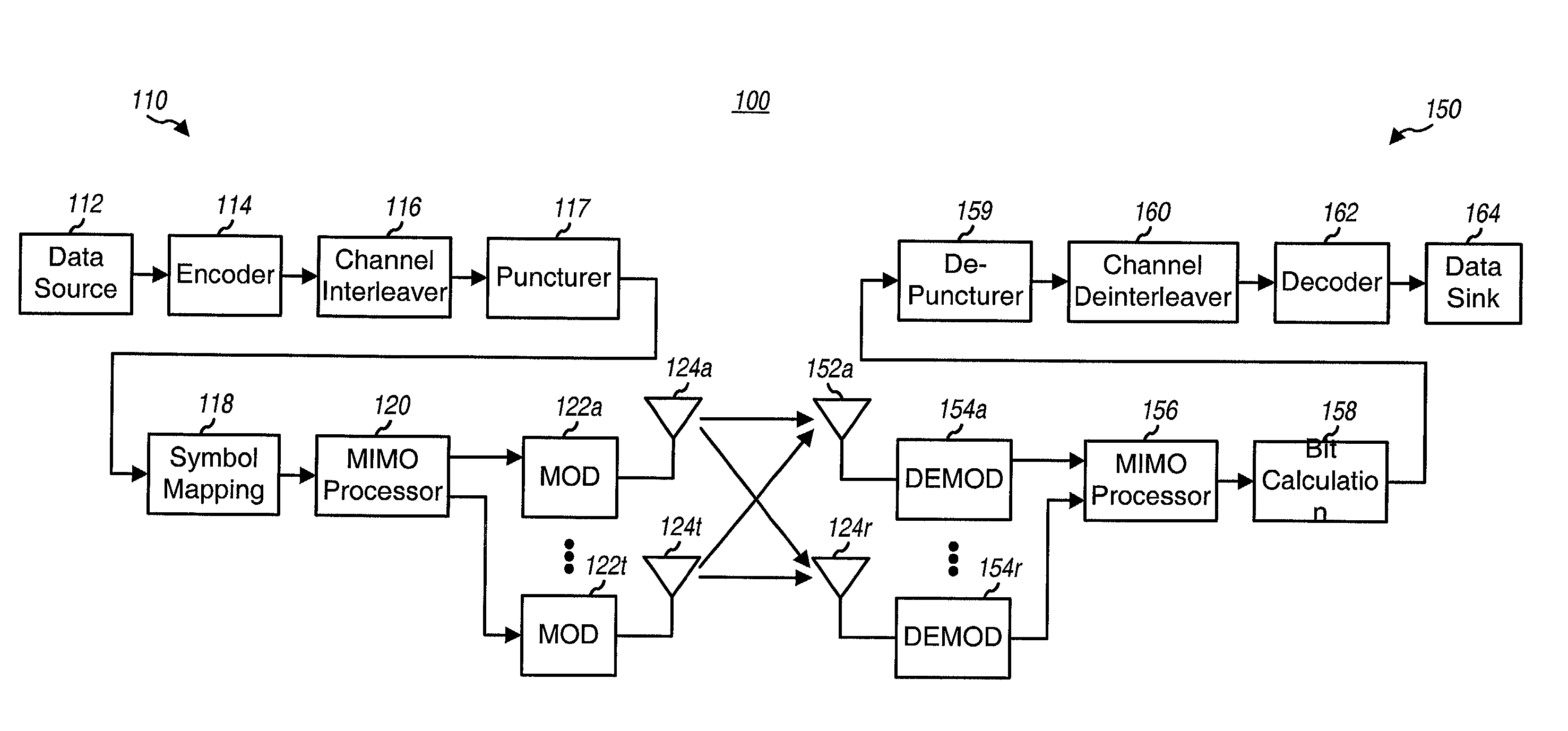
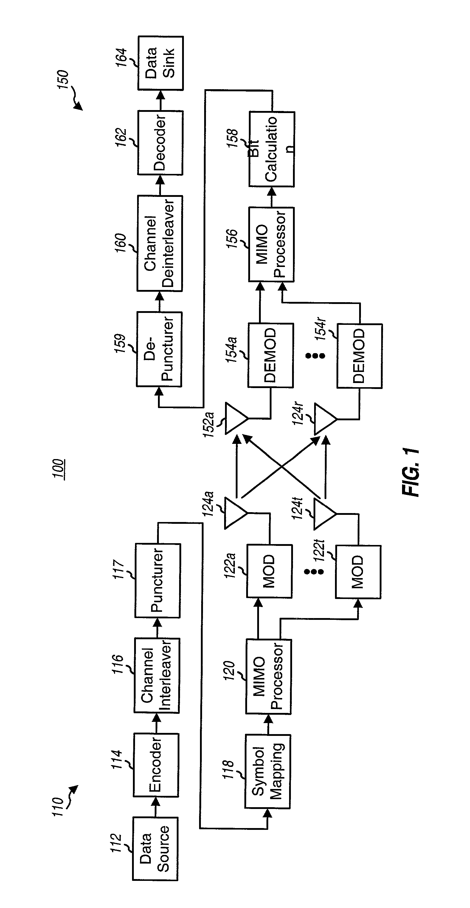
[0025] As shown in FIG. 1, communication system 100 includes a first system 110 in communication with a second system 150. Within system 110, a data source 112 provides data (i.e., information bits) to an encoder 114 that encodes the data in accordance with a particular coding scheme. The encoding increases the reliability of the data transmission. The coded bits are then provided to a channel interleaver 116 and interleaved (i.e., reordered) in accordance with a particular interleaving scheme. The interleaving provides time and frequency diversity for the coded bits, permits the data to be transmitted based on an average SNR for the subchannels used for the data transmission, combats fading, and further removes correlation between coded bits used to form each modulation symbol, as described below. The interleaved bits are then punctured (i.e., deleted) to provide the required number of coded bits. The encoding, channel interleaving, and puncturing are described in further detail below. The unpunctured coded bits are then provided to a symbol mapping element 118.

Problems solved by technology

The different transmission capabilities of the frequency subchannels plus the time-variant nature of the capabilities make it challenging to provide an effective coding scheme capable of encoding the supported number of information bits / modulation symbol to provide the required coded bits for the subchannels

Method used


Image

  • Coding scheme for a wireless communication system
  • Coding scheme for a wireless communication system
  • Coding scheme for a wireless communication system

Examples


Embodiment Construction

[0024] FIG. 1 is a diagram of a multiple-input multiple-output (MIMO) communication system 100 capable of implementing various aspects and embodiments of the invention. Communication system 100 can be designed to implement the coding schemes described herein. System 100 can further be operated to employ a combination of antenna, frequency, and temporal diversity to increase spectral efficiency, improve performance, and enhance flexibility. Increased spectral efficiency is characterized by the ability to transmit more bits per second per Hertz (bps / Hz) when and where possible to better utilize the available system bandwidth. Improved performance may be quantified, for example, by a lower bit-error-rate (BER) or frame-error-rate (FER) for a given link signal-to-noise-plus-int-erference ratio (SNR). And enhanced flexibility is characterized by the ability to accommodate multiple users having different and typically disparate requirements. These goals may be achieved, in part, by employ...


PUM


Abstract

Coding techniques for a (e.g., OFDM) communication system capable of transmitting data on a number of "transmission channels" at different information bit rates based on the channels' achieved SNR. A base code is used in combination with common or variable puncturing to achieve different coding rates required by the transmission channels. The data (i.e., information bits) for a data transmission is encoded with the base code, and the coded bits for each channel (or group of channels with the similar transmission capabilities) are punctured to achieve the required coding rate. The coded bits may be interleaved (e.g., to combat fading and remove correlation between coded bits in each modulation symbol) prior to puncturing. The unpunctured coded bits are grouped into non-binary symbols and mapped to modulation symbols (e.g., using Gray mapping). The modulation symbol may be "pre-conditioned" and prior to transmission.

Description

[0001] I. Field[0002] The present invention relates to data communication. More particularly, the present invention relates to a novel, flexible, and efficient coding scheme for encoding data for transmission on multiple transmission channels with different transmission capabilities.[0003] II. Description of the Related Art[0004] Wireless communication systems are widely deployed to provide various types of communication such as voice, data, and so on. These systems may be based on code division multiple access (CDMA), time division multiple access (TDMA), orthogonal frequency division modulation (OFDM), or some other modulation techniques. OFDM systems may provide high performance for some channel environments.[0005] In an OFDM system, the operating frequency band is effectively partitioned into a number of "frequency subchannels", or frequency bins. Each subchannel is associated with a respective subcarrier upon which data is modulated, and may be viewed as an independent "transmi...

Claims


Application Information

Patent Timeline
IPC IPC(8): H04B7/04H04J11/00H04J99/00H04L1/00H04L27/26
CPCH04B7/0417H04B7/0632H04L1/0009H04L1/0041H04L1/005H04L1/0066H04L1/0068H04L1/0071H04L5/0023H04L5/0046H04L5/0048H04L5/006H04L27/3488H04L1/0055H04L25/03171H04L27/26
Inventor LING, FUYUNSINDHUSHAYANA, NAGABHUSHANA T.WALTON, JAY R.WALLACE, MARKFERNANDEZ, IVAN
Owner QUALCOMM INC
Learn More