
System and method of controlling airflow in an air delivery system

a technology of air delivery system and control system, which is applied in the direction of efficient regulation technology, mechanical equipment, machines/engines, etc., can solve the problems of complex computation and significant processing resources, and the derived mathematical model of one blower or fan cannot produce controlled cfm representations for all blower geometries, sizes, and air conditioning systems

Inactive Publication Date: 2003-03-06
SULFSTEDE LOUIS E
View PDF10 Cites 30 Cited by
  • Summary
  • Abstract
  • Description
  • Claims
  • Application Information

AI Technical Summary

Problems solved by technology

However, the derived mathematical model for one blower or fan cannot produce controlled CFM representations for all blower geometries, sizes, or air conditioning systems.
Using such a generalized mathematical model, requires complex computations and significant processing resources.
Thus, to facilitate the preferred airflow process control within air conditioning systems, costly resources must be used.
However, Young does not teach or suggest a system or method of determining and implementing a particular CFM based on torque and speed by utilizing mathematical computations developed utilizing several discrete airflows within regions or bins within a designated range.
Young suffers from the disadvantage of requiring an air conditioning controller to utilizing complex mathematical computations to select the desired CFM based on static pressure across the entire operation region.

Method used


Image

  • System and method of controlling airflow in an air delivery system
  • System and method of controlling airflow in an air delivery system
  • System and method of controlling airflow in an air delivery system

Examples


Embodiment Construction

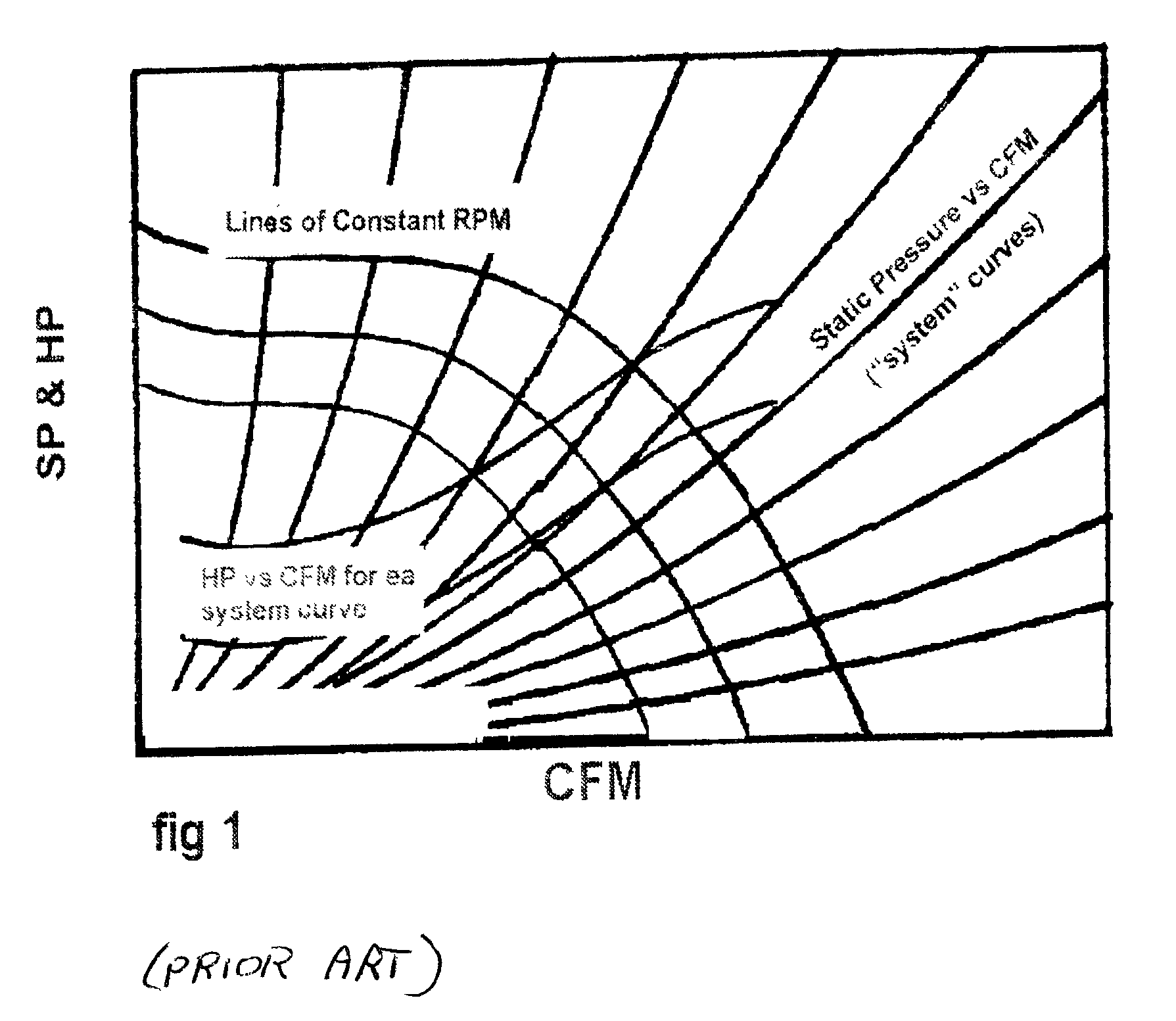
[0023] FIG. 1 is a graphical representation of a plurality of rates of air flow (CFMs-cubic feet per minute) based upon speed and horsepower of a motor within an existing air conditioning system. To produce a specific airflow performance from a mathematical model, a blower's specified performance data or an air conditioning system and its motor characteristics are measured and quantified. Specifically, the blower's airflow, and the motor's speed and torque are shown in FIG. 1. The torque and speed of the blower are related to the restriction on the blower at a given airflow. From this specific torque and speed of the motor, an air flow rate is derived. In order to find the specific characteristics of each individual and unique blower system, airflow is measured in a laboratory across the full range of external restrictions. The measured data is used to create a mathematical formula of the form CFM=f(T,S) that serves as a model to describe the physics of the process. There are variou...


PUM


Abstract

A system and method of controlling airflow within an air delivery system. The method begins by identifying and measuring a particular air conditioning system's blower characteristics. A mathematical relationship for finding a particular CFM based on torque and speed is developed utilizing several discrete airflows within regions or bins within a designated range. The mathematical model is employed by a controller of the air conditioning system for controlling CFM. Additionally, the method may optionally change from an airflow control mode to a blower speed or torque control mode when restrictions are placed upon the air conditioning system.

Description

[0001] This utility application claims the priority date of Provisional Patent Application Serial No. 60 / 317,323 filed Sep. 5, 2001 and is hereby incorporated by reference.[0002] 1. Technical Field of the Invention[0003] This invention relates to the control of delivered air in air delivery systems and, more particularly, to a system and method of controlling airflow by a discrete bin airflow mathematical model in an air delivery system.[0004] 2. Description of Related Art[0005] There have been many systems implemented to optimize airflow within an air conditioning system. Typically, the air conditioning system includes a device to condition the temperature of the air, with the delivery rate of the conditioned air regulated by a motor driving a blower. Many factors affect the amount of air and the rate of air delivery (often measured as CFM-cubic feet per minute). Such factors include the blower wheel design and type, the motor's speed and torque, restrictions associated with the bl...

Claims


Application Information

Patent Timeline
IPC IPC(8): F01P7/04F04D27/02
CPCF01P7/048F04D27/004Y02B30/70
Inventor SULFSTEDE, LOUIS E.
Owner SULFSTEDE LOUIS E
Learn More