
Power characteristic of a radio transmitter

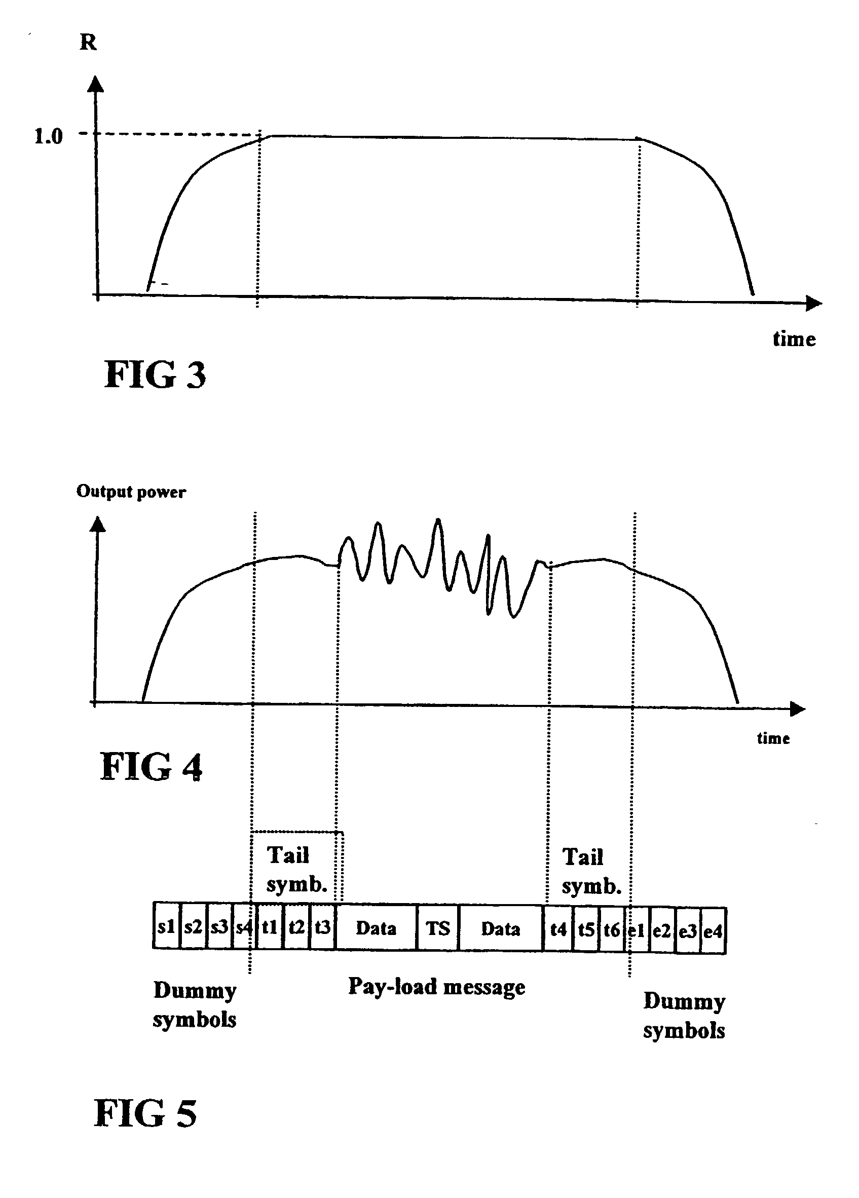
a radio transmitter and power characteristic technology, applied in the direction of transmission monitoring, power management, wireless communication, etc., can solve the problems of temperature drift of amplifying components, system noise risk, and spectrum spreading

Inactive Publication Date: 2003-02-27
TELEFON AB LM ERICSSON (PUBL)
View PDF6 Cites 29 Cited by
  • Summary
  • Abstract
  • Description
  • Claims
  • Application Information

AI Technical Summary

Problems solved by technology

Uncontrolled power during these phases may create switching transients which results in spectrum spreading.
This spreading could influence on other frequencies and cause interference.
Still there is a risk of introducing noise in the system.
Another problem factor which the prior art solutions is the temperature drift of the amplifying components.
However, variable gain amplifiers are used and the noise problem is not avoided.
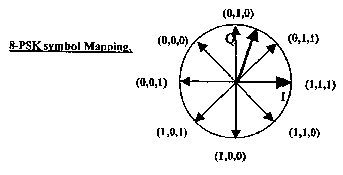
The above mentioned prior art is not suitable for applications with linear modulation techniques like QPSK, 8-PSK, QAM etc, which also contain amplitude variations.
Otherwise the power regulation will cancel out the amplitude variations and thus destroy the message sent.
However, the switching in and out of the control will introduce transients in the output power disturbing other users of the system.

Method used


Image

  • Power characteristic of a radio transmitter
  • Power characteristic of a radio transmitter
  • Power characteristic of a radio transmitter

Examples


Embodiment Construction

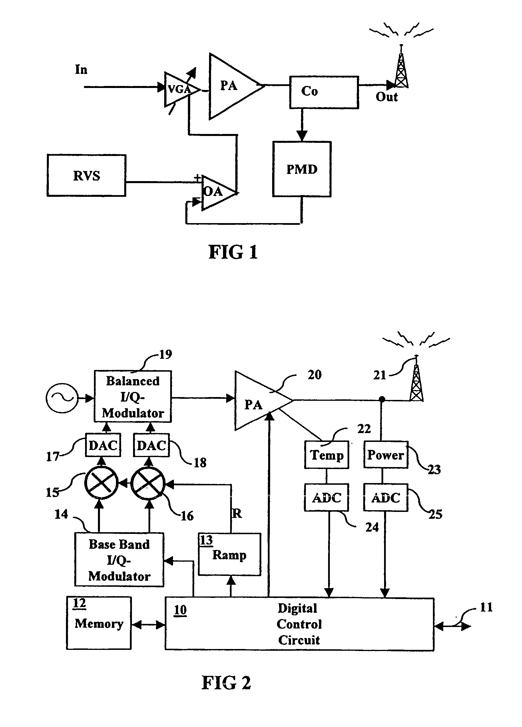
[0026] Referring to FIG. 2 a schematic drawing of a system for transmitting a radio message, according to the invention, is shown. The system comprises a digital control circuit, DCC, 10, connected to system interface 11 which delivers the transmitting information. The DCC includes a memory 12 for storing data related to the transmission, like carrier frequency, power level, burst form functions and temperature of the transmitter amplifiers. The DCC controls a ramp forming generator 13 and an I- and Q-base-band digital modulator 14, including a data to symbol mapper. In a combining device illustrated as multipliers 15, 16 the I / Q values are combined with the ramp function R generated by the generator 13. The combined signals are converted into analogue form in digital to analogue converters DAC, 17, 18. The DAC drives the input of an analogue balanced modulator 19. The modulated signal is amplified in a power amplifier 20 before being brought to the antenna 21.

[0027] The system in F...


PUM


Abstract

The present invention relates to radio transmission of bursts in for example a TDMA cellular radio system. The burst starts with a ramping up period, ends with a corresponding ramping down ramping down period and with the pay-load information therebetween. The ramp form is created in a ramp generator (13) which gives a multiplication value to multiply the digital information to be transmitted in multipliers (15, 16). The multiplied values are converted into analogue form and amplified before being transferred to the antenna (21). Output power and temperature of the transmitting equipment are measured (22, 23) and used to update the output power levels during the next burst.

Description

[0001] The present invention relates to the radio transmitter field and particularly to the characteristic of the output power when sending messages in the form of bursts.DESCRIPTION OF RELATED ART[0002] In modern wireless systems like digital cellular telephone systems some form of control of the output power have to be utilised. Especially in TDMA-systems where the channels are allocated to the users in the form of time slots with messages transmitted as bursts with short duration, it is not just the general power level which has to be controlled, but also the power in the start and stop phases. Uncontrolled power during these phases may create switching transients which results in spectrum spreading. This spreading could influence on other frequencies and cause interference. Thus, there is also a special need for control of the ramping up and down of the power in each burst.[0003] The digital information is conventionally transferred into a vector model with in phase components I...

Claims


Application Information

Patent Timeline
Patent Type & Authority Applications(United States)
IPC IPC(8): H03G3/00H03G3/30
CPCH03G3/001H03G3/3047H04W52/50H03G2201/708H04W52/52
Inventor SAHLMAN, KARL GOSTAERIKSSON, HANS
Owner TELEFON AB LM ERICSSON (PUBL)
Learn More