
Video-based surgical targeting system

a surgical targeting and video technology, applied in the field of video-based surgical targeting systems, can solve the problems of difficult physical location of a particular anatomical structure, difficult identification with the naked eye, and small structures of interest,

Inactive Publication Date: 2003-02-13
MEDICAL MEDIA SYSTEMS
View PDF0 Cites 28 Cited by
  • Summary
  • Abstract
  • Description
  • Claims
  • Application Information

AI Technical Summary

Benefits of technology

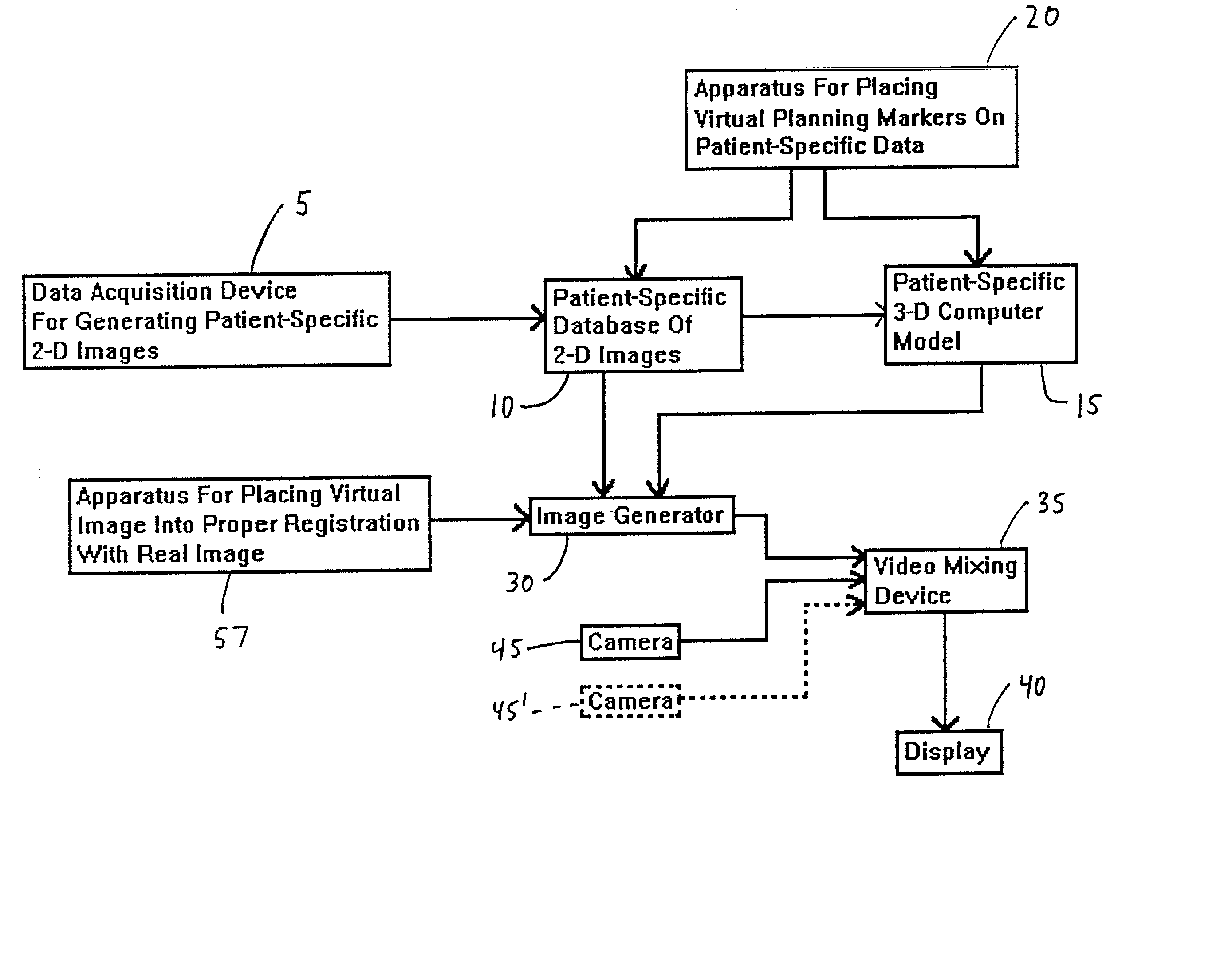
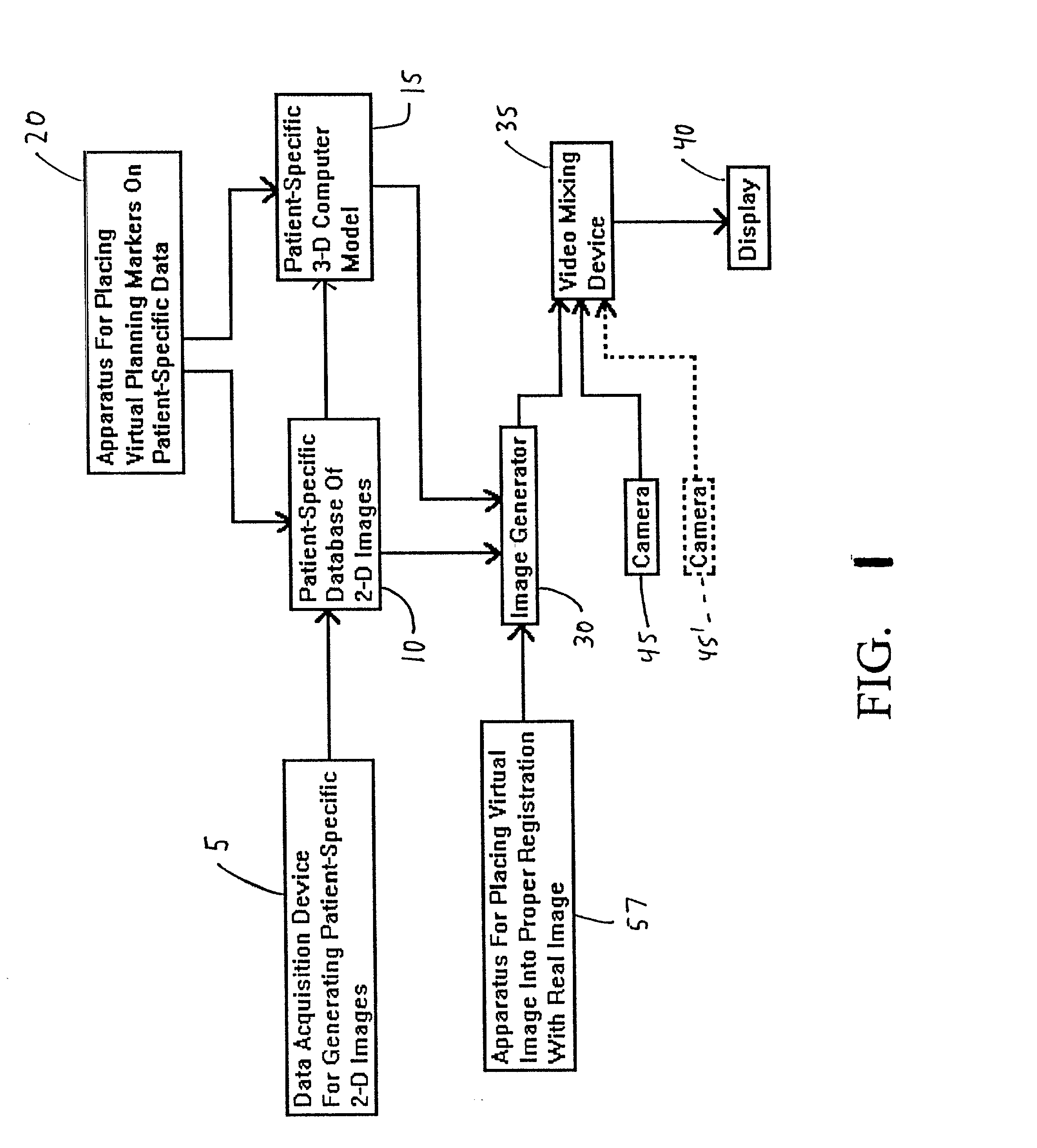
[0009] Still another object of the present invention is to provide a video-based surgical targeting system which allows a physician to view the aforementioned patient-specific 2-D images on a display in any desired access sequence.
[0074] Furthermore, another tracker 80 can be positioned on a surgical instrument 85. In this case, tracker 80 will provide M.sub.TI, where M.sub.TI represents the matrix transformation from tracker base 75 to instrument 85. Accordingly, once M.sub.PT and M.sub.TI are known, it is possible to solve for M.sub.PI, where M.sub.PI represents the matrix transformation from the patient's anatomical structure 60 to instrument 85. With M.sub.PI known, it is then possible to track the position of surgical instrument 85 relative to anatomical structure 60. This is a very powerful tool, since it allows a virtual representation of surgical instrument 85 to be accurately added to the properly registered virtual and real images presented on display 40, i.e., it allows a virtual representation of instrument 85 to be shown in proper registration with a real image of anatomical structure 60 on display 40.

Problems solved by technology

Furthermore, in many cases the structures of interest may be quite small and difficult to identify with the naked eye.
While the information generated by the aforementioned scanning devices is generally of great benefit to physicians, certain significant limitations still exist.
For one thing, it can be very difficult for a physician to physically locate a particular anatomical structure during a medical procedure, even when that structure is readily identifiable in a scanned image.
This may be because the structure is very small and difficult to see with the naked eye, or because it is not readily visible against a particular background, or because it is itself located within an internal organ or other internal body structure, etc.
For another thing, even when the structure of interest is successfully located by the physician, it can sometimes still be extremely difficult for the physician to reliably direct a medical instrument to that structure.
This may be because the structure is quite small and difficult to target accurately, or because intervening body structure mandates a complex approach, etc.

Method used


Image

  • Video-based surgical targeting system
  • Video-based surgical targeting system
  • Video-based surgical targeting system

Examples


Embodiment Construction

[0077] It is, of course, possible to modify the preferred embodiments disclosed above without departing from the scope of the present invention.

[0078] Thus, for example, while only one camera 45 has been disclosed above, it should be appreciated that two or more cameras 45 may be used. Furthermore, it should also be appreciated that camera 45 may comprise a video camera, or it may comprise an endoscope, or it may comprise some other type of real-time image capturing means, e.g. it may comprise an ultrasound device.

[0079] Additionally, it should be recognized that the system might be adapted so that patient-specific database 10 comprises non-2-D images, e.g. database 10 might comprise one or more images generated by a Cyberware 3-D scanner.

[0080] Alternatively, patient-specific 3-D computer model 15 might be omitted from the apparatus entirely. In this case, the virtual images could be generated from patient-specific database 10 by image generator 30 through the use of a volume rende...


PUM


Abstract

A video-based surgical targeting system for targeting anatomical structures within a patient.

Description

[0001] This invention relates to surgical systems in general, and more particularly to surgical targeting systems.[0002] Many medical procedures must be carried out at an interior site which is normally hidden from the view of the physician. In these situations, the physician typically uses some sort of scanning device to examine the patient's anatomy at the interior site prior to, and in preparation for, conducting the actual procedure itself. These scanning devices typically include MRI devices, CT scanners, X-ray machines, ultrasound devices and the like, and serve to provide the physician with a preliminary knowledge of the patient's internal anatomical structure prior to commencing the procedure. The physician can then use this information to plan the procedure in advance, taking into account patient-specific anatomical structure. In addition, the physician can also use the information obtained from these scans to more precisely identify the location of selected structures (e.g...

Claims


Application Information

Patent Timeline
Patent Type & Authority Applications(United States)
IPC IPC(8): A61B19/00G09B23/28
CPCA61B19/52A61B19/5212A61B19/5244A61B19/56A61B2019/502A61B2019/505A61B2019/5255A61B2019/5289A61B2019/5291A61B2019/5295G09B23/28Y10S128/92Y10S128/922A61B2034/102A61B90/36A61B2034/2055A61B2090/367A61B34/20A61B34/25A61B2090/364A61B90/361A61B2034/105A61B2090/365
Inventor CHEN, DAVID T.PIEPER, STEVEN D.MCKENNA, MICHAEL A.
Owner MEDICAL MEDIA SYSTEMS
Learn More