Deflection compensation roll

a technology of deflection compensation and roll, which is applied in the direction of manufacturing tools, mechanical equipment, portable power-driven tools, etc., can solve the problems of increased operating speed, increased rotational speed of the roll jacket, and danger of resonance phenomenon

Inactive Publication Date: 2003-01-23
VOITH PATENT GMBH
View PDF16 Cites 1 Cited by
  • Summary
  • Abstract
  • Description
  • Claims
  • Application Information

AI Technical Summary

Problems solved by technology

However, the increase in the operating speed also entails an increase in the rotational speed of the roll jacket.
This leads to the roll jacket reaching critical speed ranges where there is a danger of a resonance phenomenon.
It has now been shown with some rolls that undesirable vibrations occur at rotational speeds at which they would not normally have been expected.

Method used


Image

  • Deflection compensation roll
  • Deflection compensation roll
  • Deflection compensation roll

Examples


Embodiment Construction

[0037] The particulars shown herein are by way of example and for purposes of illustrative discussion of the embodiments of the present invention only and are presented in the cause of providing what is believed to be the most useful and readily understood description of the principles and conceptual aspects of the present invention. In this regard, no attempt is made to show structural details of the present invention in more detail than is necessary for the fundamental understanding of the present invention, the description taken with the drawings making apparent to those skilled in the art how the several forms of the present invention may be embodied in practice.

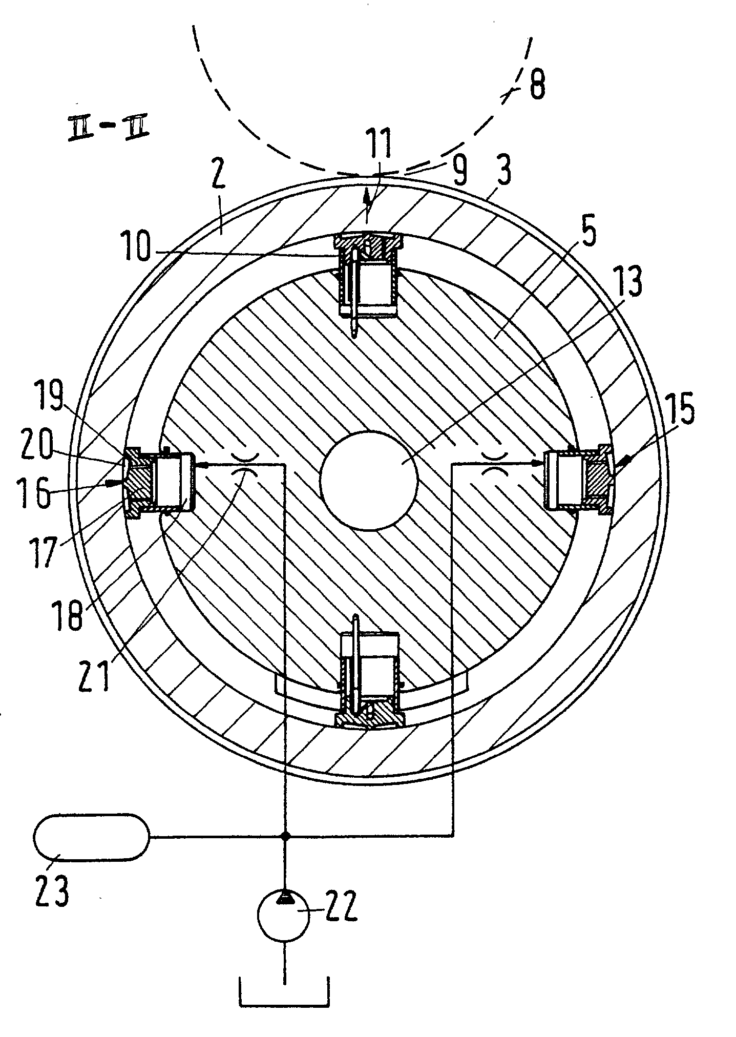
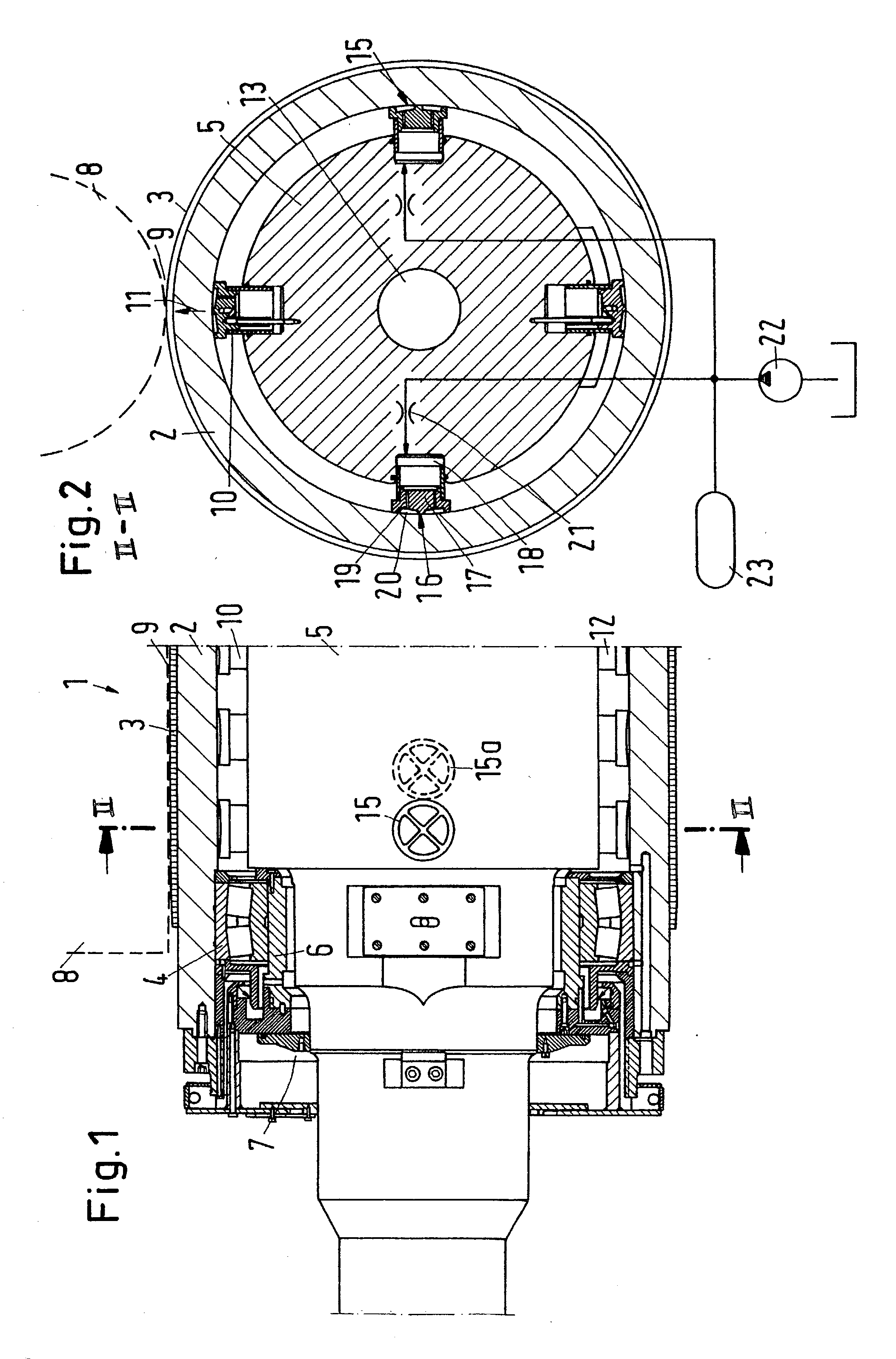
[0038] A roll 1, which is embodied as a through deflection compensation roll, features a roll jacket 2 which can be provided with an elastic coating 3 if roll 1 is to be installed in a calender as a "soft" roll. However, coating 3 can be omitted, particularly if roll 1 is to be used in a calender stack or as a "hard" rol...


PUM

PropertyMeasurementUnit
static gap heightaaaaaaaaaa
angleaaaaaaaaaa
static gap heightaaaaaaaaaa

Abstract

Deflection compensation roll and process for reducing vibrations in deflection roll. The roll includes antifriction bearings, a roll jacket supported in an area of its axial ends on the antifriction bearings, and hydraulic supports arranged to hydraulically support the roll jacket parallel to a working plane. A damping device, positioned next to each antifriction bearing, is structured and arranged to act essentially perpendicular to the working plane.

Description

[0001] The present application claims priority under 35 U.S.C. .sctn.119 of German Patent Application No. 101 22 648.9, filed on May 10, 2001, the disclosure of which is expressly incorporated by reference herein in its entirety.[0002] 1. Field of the Invention[0003] The present invention relates to a deflection compensation roll with a roll jacket which is arranged on antifriction bearings in the area of its axial ends and is hydraulically supported parallel to a working plane.[0004] 2. Discussion of Background Information[0005] Such a deflection compensation roll is known from DE 198 54 339 A1. Rolls of this kind are preferred for use as end rolls in a calender for glazing a paper web or another material web, i.e., to impinge in the nips of the calender with increased pressure, if necessary also at increased temperature. In addition to the antifriction bearings, the known roll features a hydrostatic support element that is designed to guarantee a minimum load on the antifriction b...

Claims


Application Information

Patent Timeline
Patent Type & Authority Applications(United States)
IPC IPC(8): D21G1/00D21G1/02F16C13/00
CPCD21G1/008D21G1/022Y10T29/49544F16C13/028F16C13/02
Inventor HAAG, ROLF VAN
Owner VOITH PATENT GMBH
Why Eureka
Try Eureka