Extended range power detector and amplifier and method

a power detector and amplifier technology, applied in the field of power control in communications systems, can solve the problems of complex circuits or multi-stage circuits that have difficulty in real-time operation of input signals, prior arrangements are complicated, etc., and achieve the effect of extended dynamic range of amplification and power measurement, simple structure and reliable adjustmen

Inactive Publication Date: 2003-01-09
IBM CORP
View PDF0 Cites 16 Cited by
  • Summary
  • Abstract
  • Description
  • Claims
  • Application Information

AI Technical Summary

Benefits of technology

The present invention provides a simplified feedback system to control a voltage control attenuator or voltage control variable gain amplifier in an extended range amplifier. This system allows for the adjustment of extended dynamic range of amplification and power measurement. The selection of reference level of the attenuator or amplifier determines the gain of the amplifier. The technical effect of this invention is a reliable and efficient means to control the amplification of signals in an extended range amplifier.

Problems solved by technology

The technical problem addressed in this patent text is the need for a circuit that can handle amplification for a wide range of input signals, including high-speed data transmission, while providing a simplified architecture for controlling power output and measuring power. The text also mentions the importance of providing power ramping and conforming to mobile Global System For Mobile Communications Standards (GSM) standards in various applications such as CDMA and RSSI receivers.

Method used


Image

  • Extended range power detector and amplifier and method
  • Extended range power detector and amplifier and method
  • Extended range power detector and amplifier and method

Examples


examples

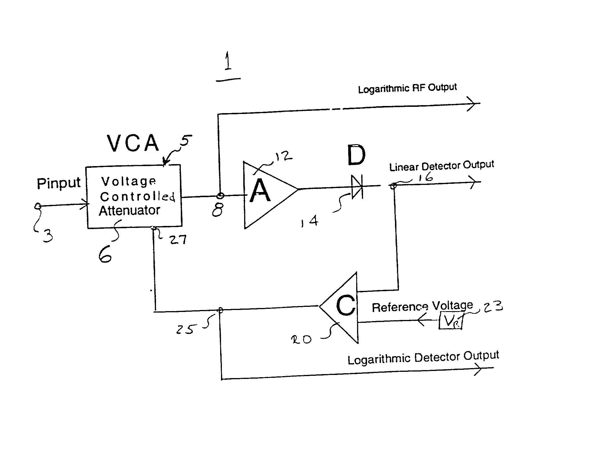
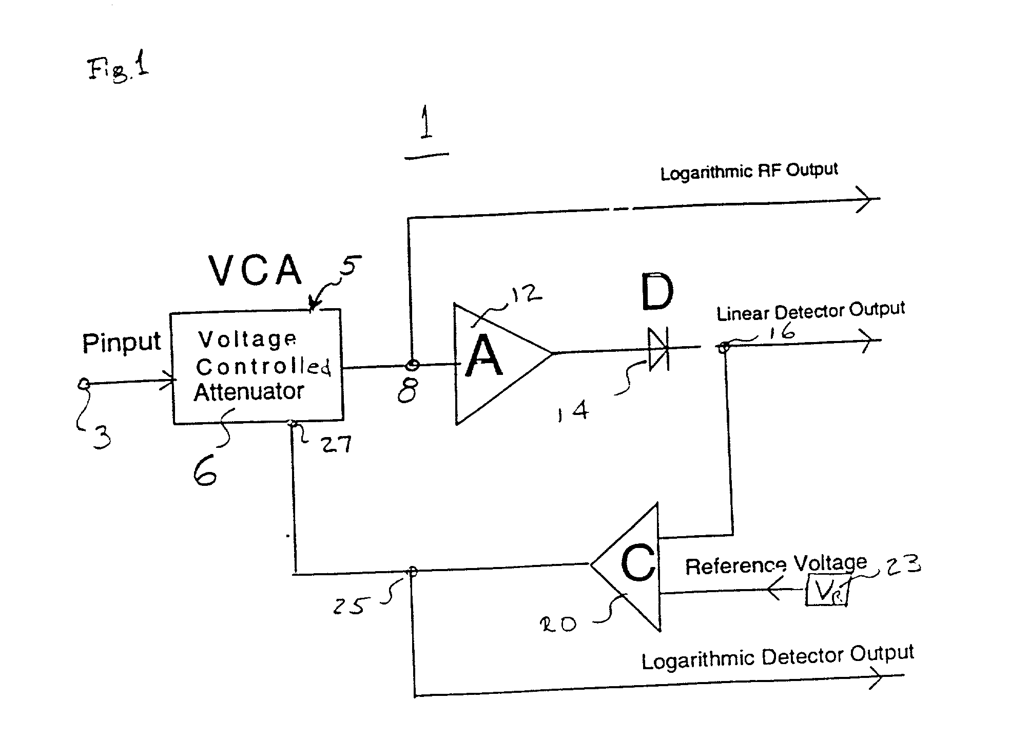
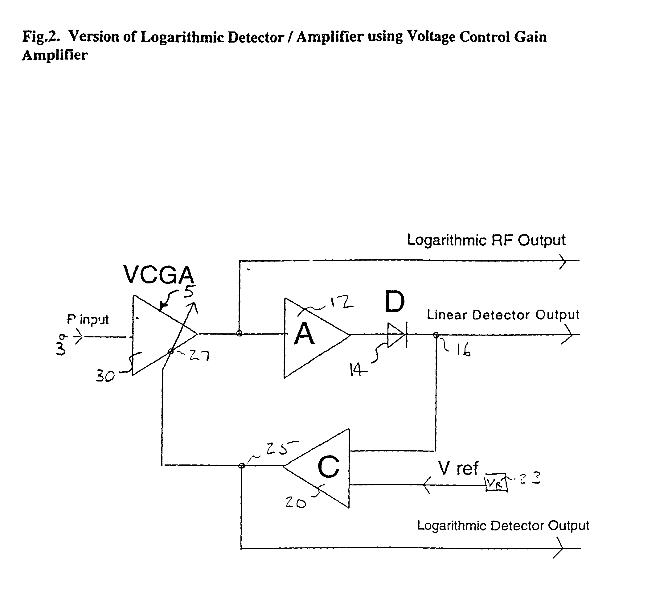
[0019] Assuming following parameters of the circuit components:

[0020] VCA insertion loss (minimum attenuation) IL_min=3 db

[0021] VCA control characteristic: -20 dB / V

[0022] VCA range: 60 dB

[0023] Gain of the Amplifier A: G-63 dB

[0024] Detector: for P_in_det=0 dBm V_det_out=1 V at 1000 ohm

[0025] The following table shown signals levels across the circuit for input signal in range from -70 dBm to +10 dBm:

1 Power at Linear VCA output Power at Detector P_in[dBm] [dBm] Detector input Output[V] Low Output -70 -73 -10 0.32 0 -60 -63 0 1 0 -50 -63 0 1 0.5 -40 -63 0 1 1 -30 -63 0 1 1.5 -20 -63 0 1 2 -10 -63 0 1 2.5 0 -63 0 1 3 10 -53 10 3.16 3

[0026] What is thus provided is an efficient, simple extended dynamic range power amplifier and an extended dynamic range power detector. It will be understood that by those skilled in the art various changes in form and detail may be made in the particular circuits illustrated and method described without the departing from the spirit and scope of the i...


PUM


Abstract

In an extended range amplifier, a simplified feedback system is provided to control a voltage control attenuator (or voltage control variable gain amplifier). The feedback loop may be embodied in analog or digital form. An input signal is applied to a variable gain or variable attenuating amplifier and, preferably, to a linear diode detector. The system logarithmic output is taken from the variable controlled device, and the linear diode detector supplies a linear output. The linear output from the diode detector is compared with a reference level. A resulting error signal is used to control the attenuation of the voltage control attenuator. In this matter, the simplified, reliable adjustment of extended dynamic range of amplification and power measurement are provided. The selection of reference level of the attenuator or amplifier will determine the gain of the amplifier.

Description


Claims


Application Information

Patent Timeline
Owner IBM CORP
Why Eureka
Try Eureka