
Multi-dimensional micro-electromechanical assemblies and method of making same

Inactive Publication Date: 2002-11-21
BRIGHT VICTOR +6
View PDF7 Cites 32 Cited by
  • Summary
  • Abstract
  • Description
  • Claims
  • Application Information

AI Technical Summary

Problems solved by technology

A conventional MEMS device could provide the array of mirrors, but they would be parallel to the surface and therefore incapable of steering a beam on command.
Accordingly, this conventional technique for fabricating 3D MEMS structures provides a low yield of devices at high cost.
While encouraging results have been obtained under laboratory conditions, this technique has not yet been perfected so as to yield a large number of 3D MEMS devices manufactured to tight tolerances at low-cost.
Although surface tension and shrinkage assembly of MEMS have been described previously by Green et al. and Syms (Green et al., Journal of Micro-electromechanical Systems, 4(4):170-176, December 1995; Syms, J. Microelectromechanical Systems, 8(4): 448-455, December 1999), the rotation angle precision of the previously described assembly techniques has been limited.

Method used


Image

  • Multi-dimensional micro-electromechanical assemblies and method of making same
  • Multi-dimensional micro-electromechanical assemblies and method of making same
  • Multi-dimensional micro-electromechanical assemblies and method of making same

Examples


Embodiment Construction

[0040] Illustrative embodiments and exemplary applications will now be described with reference to the accompanying drawings to disclose the advantageous teachings of the present invention.

[0041] While the present invention is described herein with reference to illustrative embodiments for particular applications, it should be understood that the invention is not limited thereto. Those having ordinary skill in the art and access to the teachings provided herein will recognize additional modifications, applications, and embodiments within the scope thereof and additional fields in which the present invention would be of significant utility.

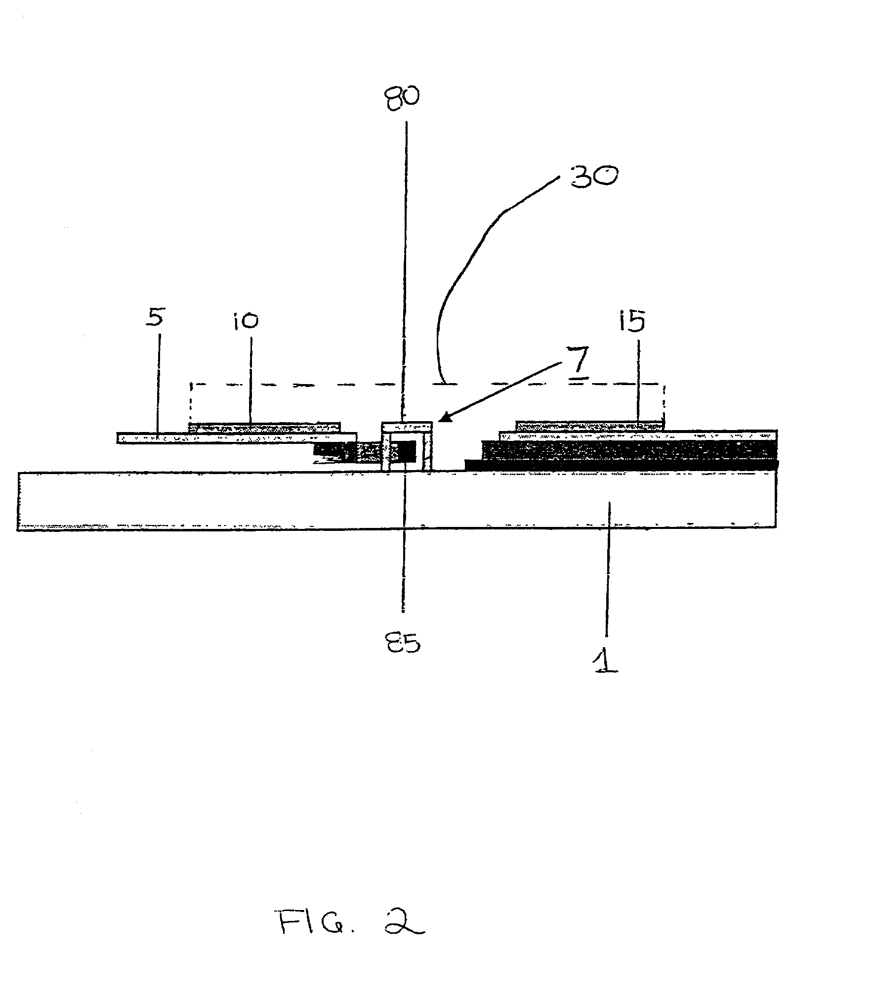
[0042] FIG. 1 is a top view of an illustrative embodiment of a multi-dimensional micro-electromechanical structure implemented in accordance with the teachings of the present invention. In accordance with the present teachings, a MEMS element (5) is attached to a substrate (1) via at least one hinge (7). A first wettable pad (10) is attached to the...


PUM


Abstract

A multi-dimensional, micro-electromechanical assembly and the method of fabricating same. The invention enables an assembly of three-dimensional (3D) microelectromechanical systems (MEMS) using surface tension or shrinkage self assembly. That is, the invention provides a surface tension self assembly technique for rotating a MEMS element with a controlled amount of deformation to a selected angle out of the plane of a substrate. In accordance with the inventive method, multi-dimensional, micro-electromechanical assemblies are fabricated by providing a phase change material on at least one substantially planar structure mounted in a first orientation. A phase change is induced in the phase change material whereby the phase change material changes from a first state, in which the structure is disposed in the first orientation, to a second state, in which the structure is disposed in a second orientation. The MEMS elements may be fabricated using conventional surface micromachining techniques. In the illustrative embodiment, each MEMS element is attached to a substrate by at least one hinge which allows rotation of the MEMS element out of the plane of the substrate to a selected angle. To enable mass assembly of the MEMS elements, the MEMS elements are rotated to the selected angle using either surface tension forces of a liquid phase change material or shrinkage of a solid phase change material. In the illustrative embodiment, the phase change material is solder and the step of inducing a phase change in the phase change material includes the step up applying heat.

Description

[0001] This application claims the benefit of a U.S. Provisional Application filed May 18, 2001, Serial No. 60 / 292,137 by Kevin Harsh, et al. for Controlled Surface Tension or Shrinkage Assembly of 3D MEMS.[0003] 1. Field of the Invention[0004] The present invention relates to micro-electromechanical (MEMS) assemblies. More specifically, the present invention relates to systems and methods for fabricating MEMS assemblies.[0005] 2. Description of the Related Art[0006] Micro-electromechanical structures are planar structures on a substrate in accordance with conventional integrated circuit fabrication techniques. Three dimensional micro-electromechanical structures (3D MEMS) are used to reflect energy and optical, microwave, fluidic and a variety of other applications. In an optical cross-connect switch used in a telecommunications application, for example, a micro-mirror may be required to steer a laser beam using a single microchip. This requires an array of mirrors that are normal ...

Claims


Application Information

Patent Timeline
IPC IPC(8): B81B3/00G02B26/08
CPCG02B26/0841B81B3/0062
Inventor BRIGHT, VICTORHARSH, KEVINKLADITIS, PAULLEE, YCZHANG, WENGEDUNN, MARTIN L.ZHANG, YANHANG
Owner BRIGHT VICTOR
Learn More