
Hydroponic apparatus and method

a technology of hydroponic equipment and water storage tank, applied in botany apparatus and processes, agriculture, gas emission reduction, etc., can solve the problems of increasing the mass of the system, requiring expensive pumps and plumbing, and large amounts of material and space in the growing bed

Inactive Publication Date: 2002-11-07
ROBINSON ALFRED JACK
View PDF0 Cites 11 Cited by
  • Summary
  • Abstract
  • Description
  • Claims
  • Application Information

AI Technical Summary

Problems solved by technology

Growing beds require large amounts of material and space, and may require expensive pumps and plumbing.
These apparatuses typically need supporting structures, such as shelving, tables, benches, or metal framing which further increase the mass of the system.
However, previous apparatuses using removable containers have also been large, and expensive.
When growing plants indoors the amount of area photosynthetically serviced by the light source limits plant productivity.
This capability may come at a high cost for equipment and a high cost for energy to run this equipment.
The semi-permanence of this apparatus also prohibits it from being easily moved.
Addressing this situation will eventually become necessary, resulting in a further expenditure of resources.
This apparatus would work best for an outdoor garden, and would make a poor choice for indoor growing.
Although the drain holes are small enough to retain gravel the plant's roots will easily fill the space between the pieces of gravel.
Root growth will eventually plug the drain holes, delaying and limiting the rise of nutrient solution within the containers.
This severely limits the capability of repositioning the container to a position more advantageous for the plant.
By its nature of construction and size this apparatus prohibits easy manageability of the plants within a confined space.
Previous hydroponic apparatuses suffered from many disadvantages when considered for use in a confined space.
An apparatus' mass and weight limits its appropriateness and suitability for indoor use.
Along with a decrease in plant health and productivity, an increase in maintenance cost would predictably result.

Method used


Image

  • Hydroponic apparatus and method
  • Hydroponic apparatus and method
  • Hydroponic apparatus and method

Examples


Embodiment Construction

--Preferred Embodiment

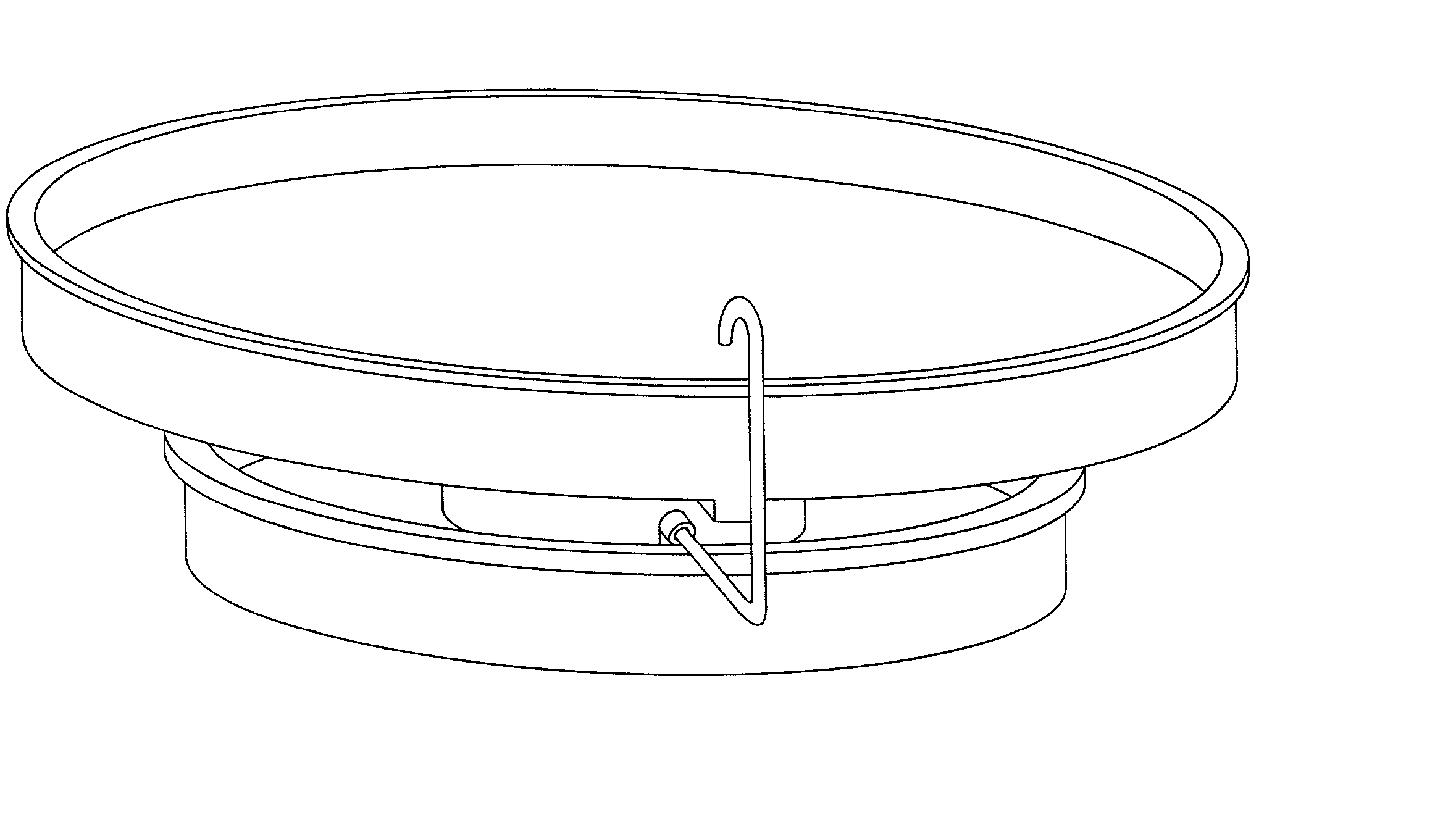
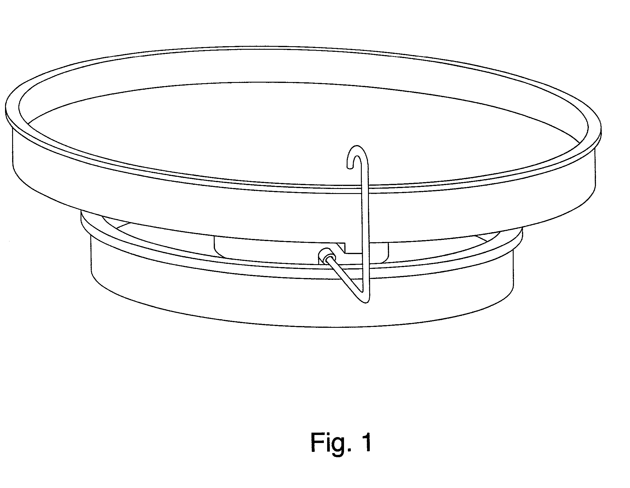
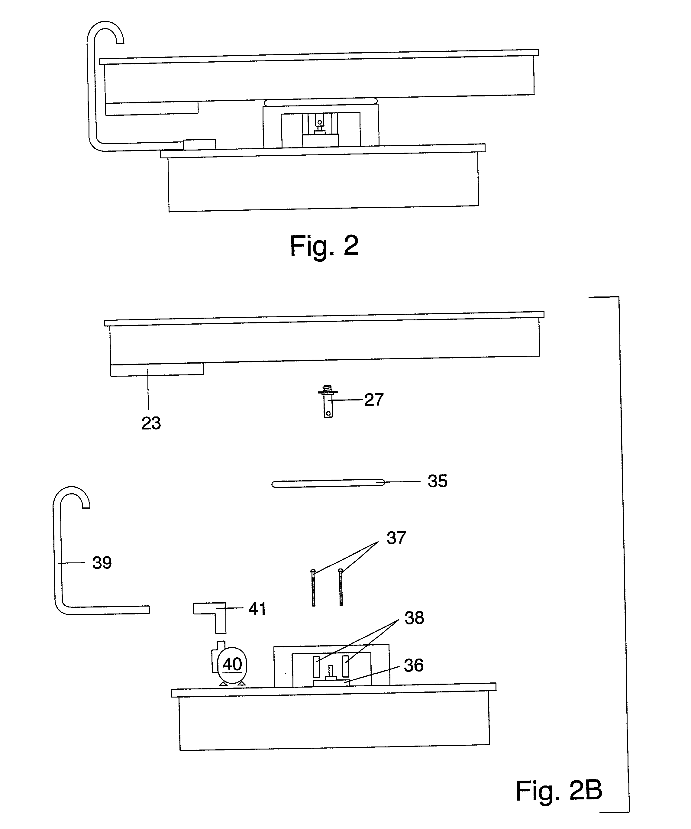
[0071] A rotating receptacle for retaining plants rooted in removable containers constitutes the primary feature of my hydroponic apparatus. FIG. 1 shows a preferred embodiment for the present invention. FIG. 2 and FIG. 2B show a frontal view and a corresponding exploded view.

[0072] The receptacle shown in FIG. 3 (perspective), FIG. 4 (top view), and FIG. 5 sectional view) will be of circumferential configuration comprising a planar rigid bottom 20 and an upstanding containment wall 21. Containment wall 21 encircles perimeter of and contiguously conjoins bottom 20. Bottom 20 has a diameter determined from a percentage of area the light source photosynthetically services. Containment wall 21 will not be taller than the height of any plant container placed in the receptacle. Containment wall 21 will be taller than the highest point of any drain opening of any plant container placed in the receptacle.

[0073] As seen in FIG. 4 and FIG. 5, the nutrient solution, once...


PUM


Abstract

There is provided, in a preferred embodiment, a hydroponic apparatus for growing plants within a confined space. Plants rooted in removable containers are placed within a receptacle that rotates on a vertical axis. During hydroponic fertilization a recirculating system delivers and transfers the nutrient solution to and from the receptacle. The plant container in the preferred embodiment allows for removal, replacement, and repositioning of plants within the receptacle. The preferred method increases the photosynthetic service area of the light source in a confined space by arranging a plurality of hydroponic apparatus beneath the light source. The combination of removable containers and rotating receptacles with a plural arrangement of apparatuses prevents algae growth, empowers the grower with plant manageability, and amplifies plant productivity.

Description

FEDERALLY SPONSORED RESEARCH[0001] Not applicable. cl SEQUENCE LISTING OR PROGRAM[0002] Not applicable.BACKGROUND--Field of Invention[0003] This invention relates to hydroponic cultivation of plants photosynthetically serviced by a confined light source. A recirculative system delivers and transfers an aqueous nutrient solution to plants rooted in removable containers.BACKGROUND--Prior Art[0004] A hydroponic apparatus provides the necessary nutrients for plant growth via an aqueous nutrient solution. Even though hydroponics eliminates soil for nutrient provision, a plant still requires a rooting medium. Growing beds require large amounts of material and space, and may require expensive pumps and plumbing. Smaller hydroponic apparatuses may use trays, pallets, or platforms instead of large growing beds. These apparatuses typically need supporting structures, such as shelving, tables, benches, or metal framing which further increase the mass of the system.[0005] Plants grown in indivi...

Claims


Application Information

Patent Timeline
Patent Type & Authority Applications(United States)
IPC IPC(8): A01G31/02
CPCA01G31/02Y02P60/21
Inventor ROBINSON, ALFRED JACK
Owner ROBINSON ALFRED JACK
Learn More