
Decoding system and method for proper interpolation for motion compensation

a motion compensation and interpolation technology, applied in the field of decoding system and interpolation proper for motion compensation, can solve the problems of hd resolution decoding complexity, spatial (pixel) domain filtering, and inability to save computation complexity in this approach, so as to avoid blurness and aliasing

Inactive Publication Date: 2002-10-17
LG ELECTRONICS INC
View PDF9 Cites 45 Cited by
  • Summary
  • Abstract
  • Description
  • Claims
  • Application Information

AI Technical Summary

Benefits of technology

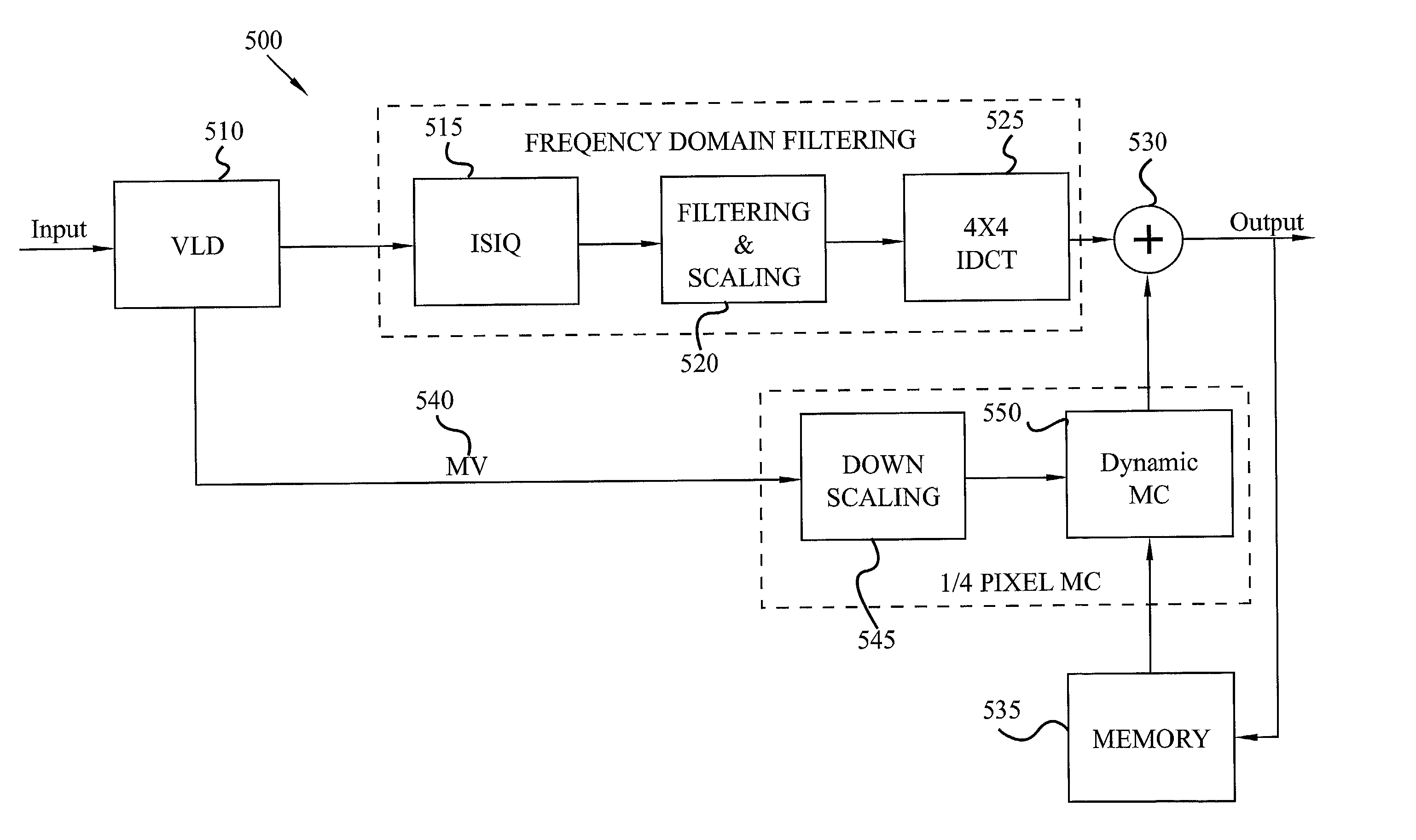
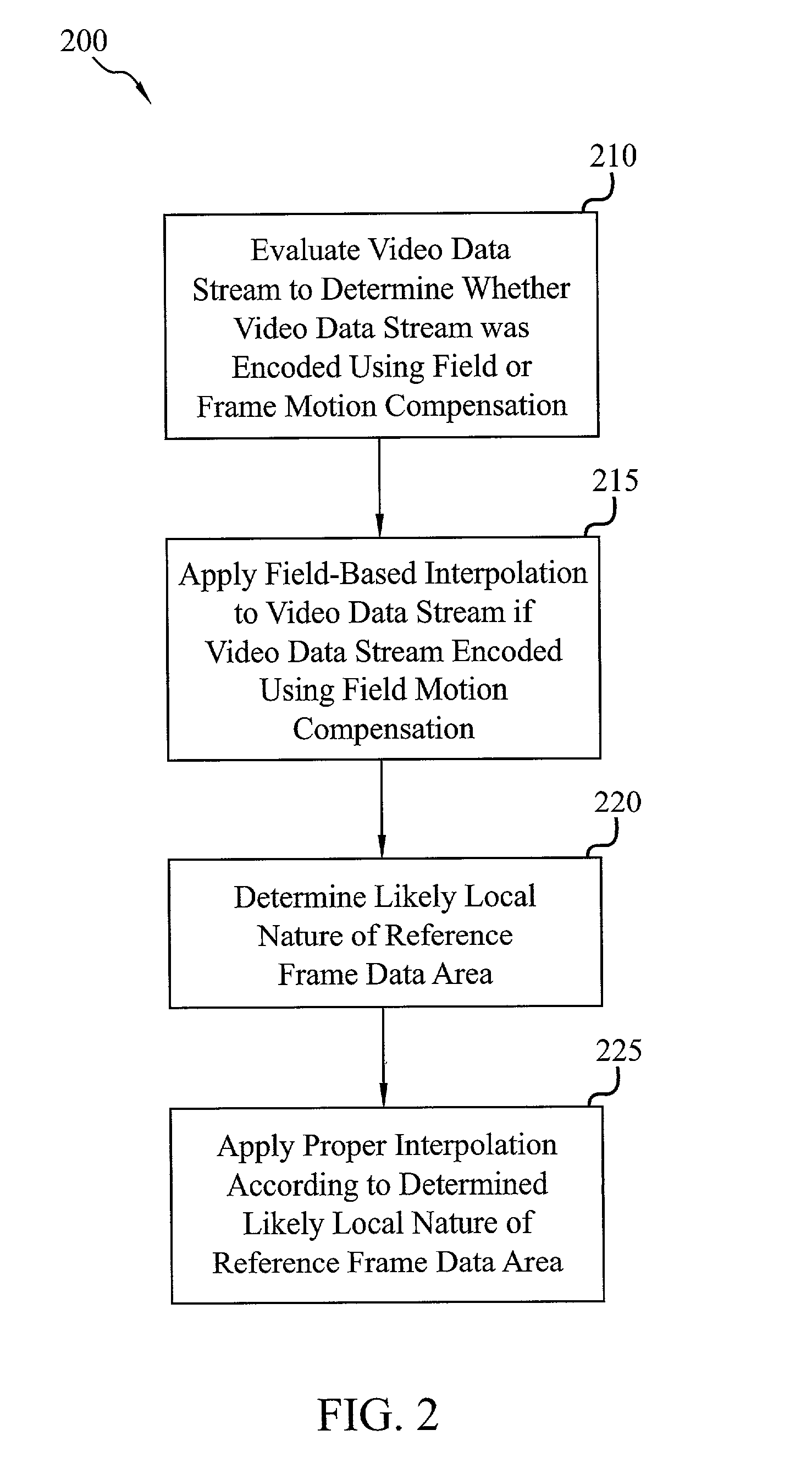
[0012] An advantage of the present invention is that it can apply frame-based interpolation or field-based interpolation dynamically in real time according to determined likely local natures of the reference frame data areas. Therefore, the present invention avoids the drawbacks of prior decoding methods and systems that choose only one mode of interpolation (field-based or frame-based) off line and apply it blindly to all frame motion compensation blocks. Specifically, the present invention avoids fetching the wrong field in the interlaced moving area and avoids blurness and aliasing in the progressive stationary area to the maximum extent.

Problems solved by technology

However, the cost for such a system is HD resolution frame memory, HD resolution decoding complexity, and spatial (pixel) domain filtering for down scaling.
However, there is no saving regarding computation complexity in this approach, since the decoding loop is still working at full (input) resolution.
Furthermore, upscaling would have to be added before motion compensation (motion compensation), which further increases the computation complexity.
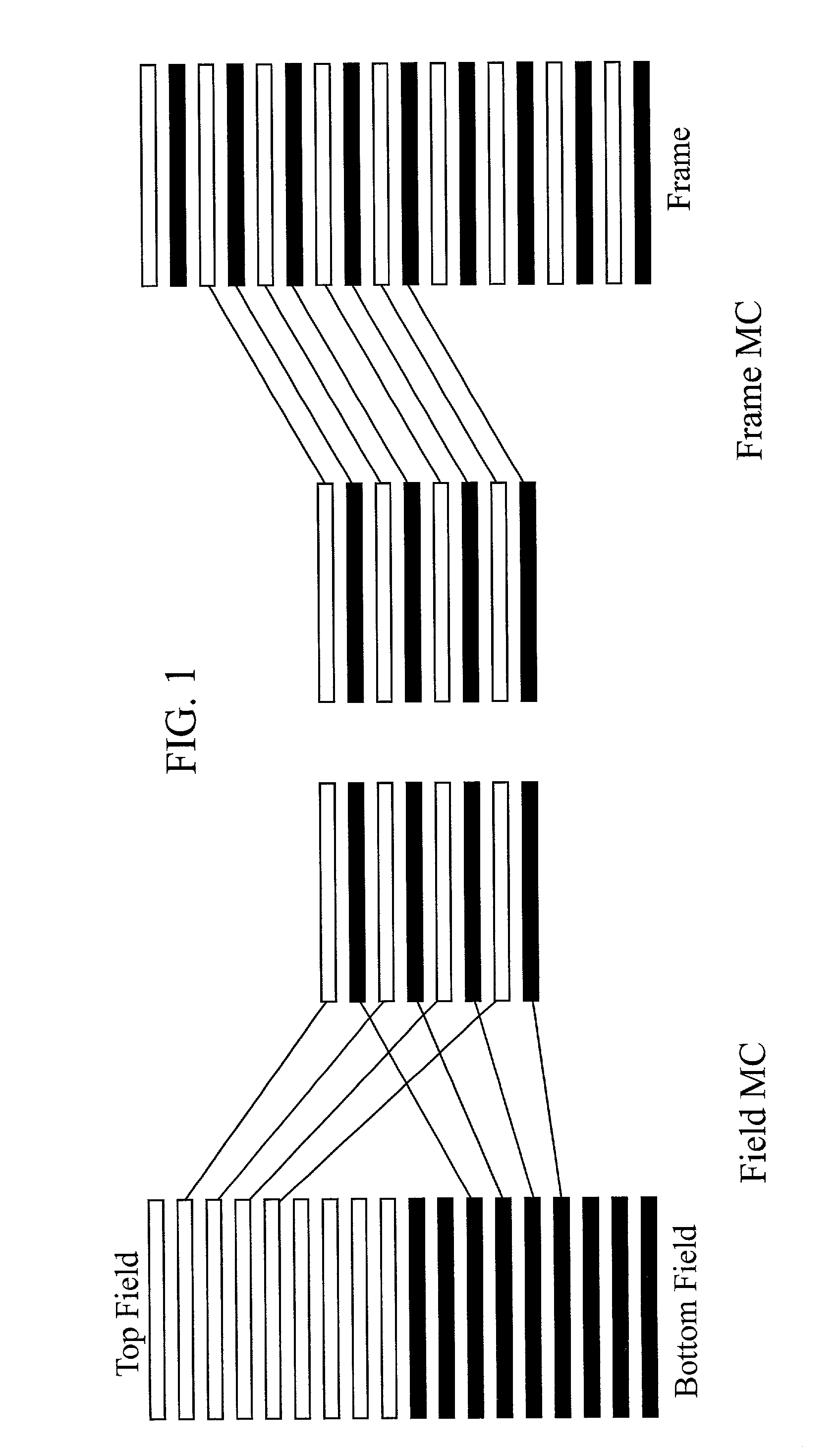
However, the interpolation in the reduced resolution reference frame can cause problems when the frame is interlaced.
If this is the case, frame-based interpolation can cause the problem of fetching the wrong field, and therefore, interpolation should be done on a field basis for frame motion compensation.
Unfortunately, whenever frame motion compensation is used standard decoding systems cannot determine locally whether the data area to be fetched contains progressive or interlaced data.
Furthermore, although there are ways to detect vertical high frequencies, to do such detection in the spatial domain is not trivial in terms of computation, and the presence of vertical high frequencies is neither a sufficient nor a necessary condition for indicating interlacing.
Both modes of interpolation, however, can cause problems when blindly applied.
Specifically, if the frame-based interpolation is applied, it risks running into the problem of fetching the wrong fields in the interlaced moving area (the visual effect is block artifact).
On the other hand, field-based interpolation faces the problem of bluriness and aliasing in the progressive stationary area.

Method used


Image

  • Decoding system and method for proper interpolation for motion compensation
  • Decoding system and method for proper interpolation for motion compensation
  • Decoding system and method for proper interpolation for motion compensation

Examples


Embodiment Construction

[0020] The present invention relates to a decoding system and method for applying proper interpolation for motion compensation to a video data stream, which can embody MPEG technology. Individuals skilled in the art of MPEG technology may wish to proceed to the Detailed Description section of this specification below. However, for those individuals who are new to MPEG technology, the following Overview Section presents many of the basic concepts and terminology useful in understanding embodiments of the present invention and their benefits and advantages.

[0021] 1. Overview

[0022] Individuals who are new to MPEG technology are directed to U.S. Pat. No. 5,122,875, which is incorporated herein by reference, for a more detailed explanation of MPEG-like encoding / decoding processes than the following summary explanation provides. Moving Picture Experts Group (MPEG) is the name of a family of standards used for coding audio-visual information (e.g., movies, video, music) in a digital compre...


PUM


Abstract

The present invention can complement and benefit virtually any method utilizing motion compensation to decode an inputted digital video data stream by determining a likely local nature of reference frame data area in the video data stream and then applying proper interpolation to the reference frame data area according to the determined likely local nature of the reference frame data area. The present invention can also complement and benefit virtually any decoding system utilizing motion compensation to decode an inputted digital video data stream by providing a motion compensation predictor that is adapted to determine a likely local nature of a reference frame data area in the video data stream and then apply proper interpolation to the reference frame data area according to the determined likely local nature of the reference frame data area.

Description

[0001] 1. Technical Field[0002] This invention relates to a decoding system and method for proper interpolation for motion compensation.[0003] 2. Background Art[0004] In some applications, a digital video data stream needs to be displayed at a smaller resolution than it has upon reception. For example, as high definition television (HDTV) is likely to become the digital TV broadcast standard in the U.S., there is a need for low cost decoding systems with High Definition (HD) capacity but Standard Definition (SD)-format output. In a standard MPEG-2 decoding system, for example, three frames of memory are needed for use in decoding the input stream, one for backward reference, one for forward reference, and a third one for the current frame. However, the frame memory size is matched to input resolution, i.e., if input is HD, 3 frames of HD size memory are required to decode the input stream.[0005] An external scaler could be added to such a standard MPEG-2 decoding system to reduce th...

Claims


Application Information

Patent Timeline
Patent Type & Authority Applications(United States)
IPC IPC(8): H04N19/50H03M7/36H04N7/01H04N19/105H04N19/139H04N19/423H04N19/513H04N19/523H04N19/625H04N19/85H04N19/91
CPCH04N7/0125H04N7/014H04N19/137H04N19/112H04N19/105
Inventor ZHONG, ZHUN
Owner LG ELECTRONICS INC
Learn More