Dark-field phase contrast imaging

a contrast imaging and dark field technology, applied in imaging devices, instruments, nuclear engineering, etc., can solve the problems of deteriorating image, inability to use strong x-ray beams for visualization of the inner structure of integrated circuits, and inability to accept the way, so as to reduce the negative influence and reduce the radiation flux

Inactive Publication Date: 2002-09-26
OSMIC
View PDF0 Cites 12 Cited by
  • Summary
  • Abstract
  • Description
  • Claims
  • Application Information

AI Technical Summary

Benefits of technology

0009] An advantage of each aspect of the present invention is the reduction of the negative influence of the direct x-ray beam in an x-ray refractive imagi

Problems solved by technology

But this way is unacceptable in many cases.
For example, strong x-ray beams cannot be used for visualization of the inner structure of integrated circuits because of their possible radiation damage, or for medical radiography for saf

Method used


Image

  • Dark-field phase contrast imaging
  • Dark-field phase contrast imaging
  • Dark-field phase contrast imaging

Examples


Embodiment Construction

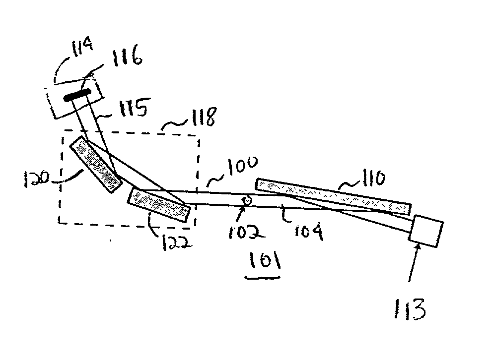
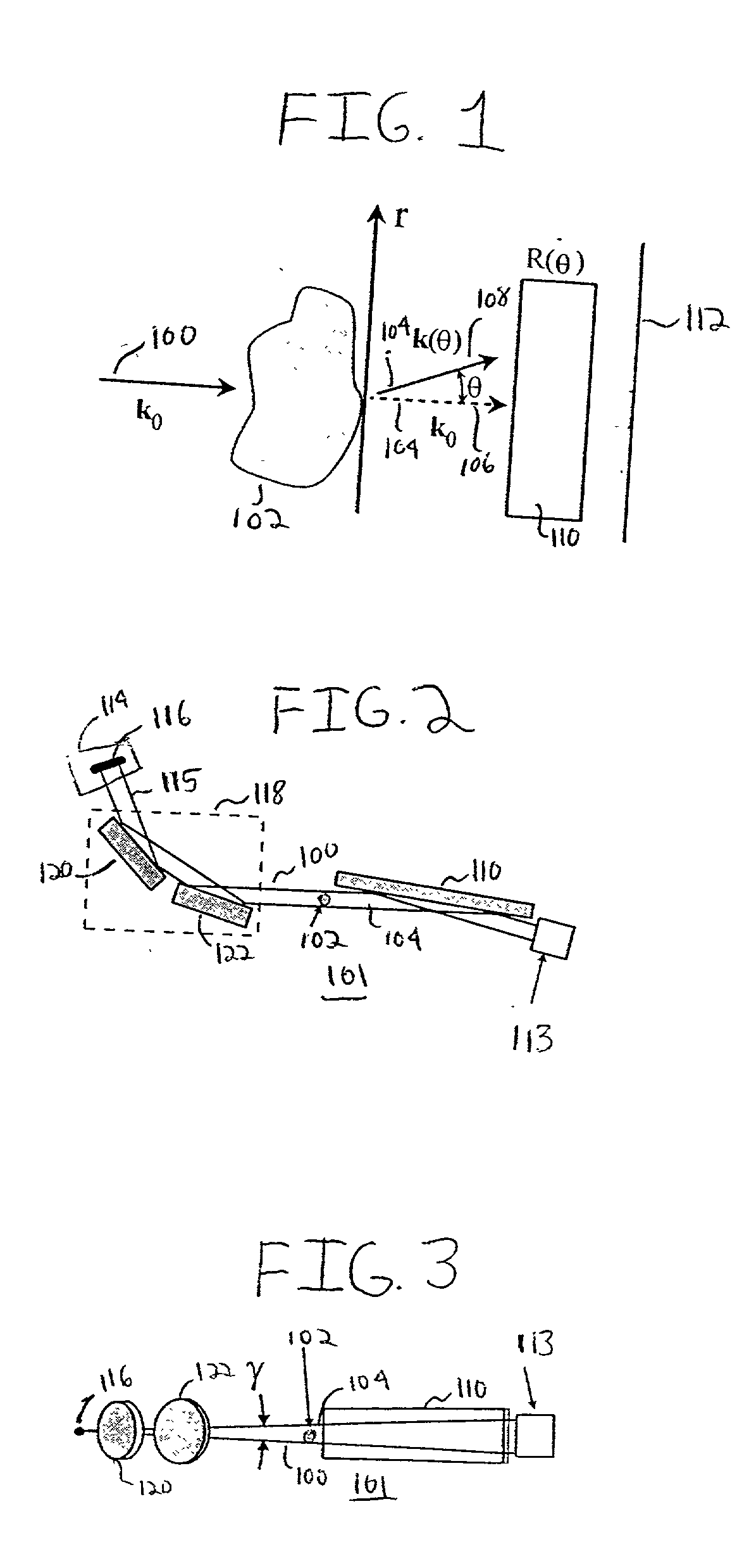
[0025] The general principles of x-ray refractive radiography are shown in FIG. 1. In particular, a parallel x-ray beam 100 with a wave vector k.sub.0 penetrates the object 102, transparent to x-rays. Because of the refraction of x-rays on the inner structure of the object 102, the output beam 104 is composed of the original wave 106 with the vector k.sub.0 and the refracted waves 108 with vectors k(.theta.) slightly declined from the initial vector k.sub.0. An analyzer 110 then differentiates the output waves 104 by their direction .theta.. Thus, the resultant image registered in the image plane 112 directly behind the analyzer 110 is formed by the intensity variations R(.theta.) proportional to the angle of refraction .theta.. Therefore, the resultant intensity distribution in the image plane 112 may be presented in the form of a sum

I(r)=R[.theta.(r)]+I.sub.0 (1)

[0026] where I.sub.0 is the intensity of the direct beam 106, which may be much greater than the useful term R[.theta.(r...


PUM


Abstract

A method of imaging an object that includes subjecting an object to a beam of radiation that is directed along a first direction and analyzing a first portion of the beam of radiation that is transmitted through the object along the first direction so that the intensity of the first portion is suppressed. Analyzing a second portion of the beam of radiation that is refracted from the object. Generating an image of the object based on the suppressed first portion of the beam of radiation and the second portion of the beam of radiation.

Description

[0001] Applicant claims, under 35 U.S.C. .sctn.119(e), the benefit of priority of: 1) the filing date of Dec. 28, 2000, of U.S. Provisional Patent Application Serial No. 60 / 258,851, filed on the aforementioned date, the entire contents of which are incorporated herein by reference, and 2) the filing date of Feb. 28, 2001, of U.S. Provisional Patent Application Serial Number 60 / 272,354, filed on the aforementioned date, the entire contents of which are incorporated herein by reference.BACKGROUND OF THE INVENTION[0002] 1. Field of the Invention[0003] The present invention relates to refractive imaging in general and x-ray refractive radiography in particular.[0004] 2. Discussion of Related Art[0005] It is well known to use X rays for imaging the internal features of objects in those cases when the object is opaque in the visible optics domain, or when extremely high spatial resolution is necessary. Traditional x-ray imaging techniques are based on the absorption contrast, i.e., on the...

Claims


Application Information

Patent Timeline
IPC IPC(8): G03H5/00
CPCG03H5/00G21K2207/005
Inventor PROTOPOPOV, VLADIMIR V.
Owner OSMIC
Why Eureka
Try Eureka