
Ultrasonic bonding method of electric wires

a technology of ultrasonic bonding and electric wires, which is applied in the direction of conductors, soldering devices, auxilary welding devices, etc., can solve problems such as deteriorating bonding

Inactive Publication Date: 2002-09-19
YAZAKI CORP
View PDF0 Cites 24 Cited by
  • Summary
  • Abstract
  • Description
  • Claims
  • Application Information

AI Technical Summary

Problems solved by technology

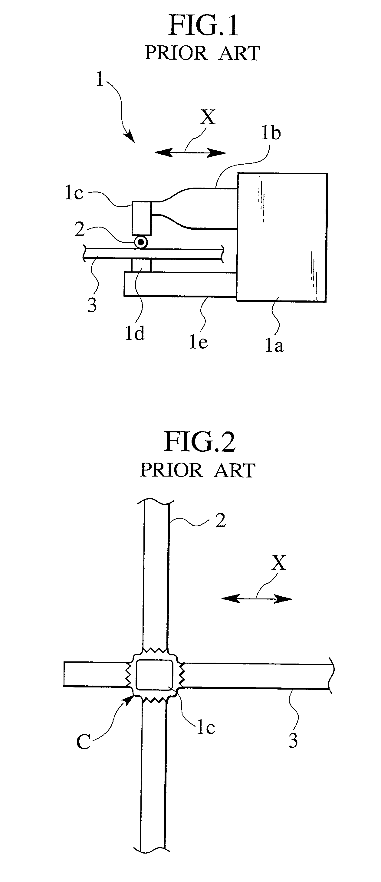
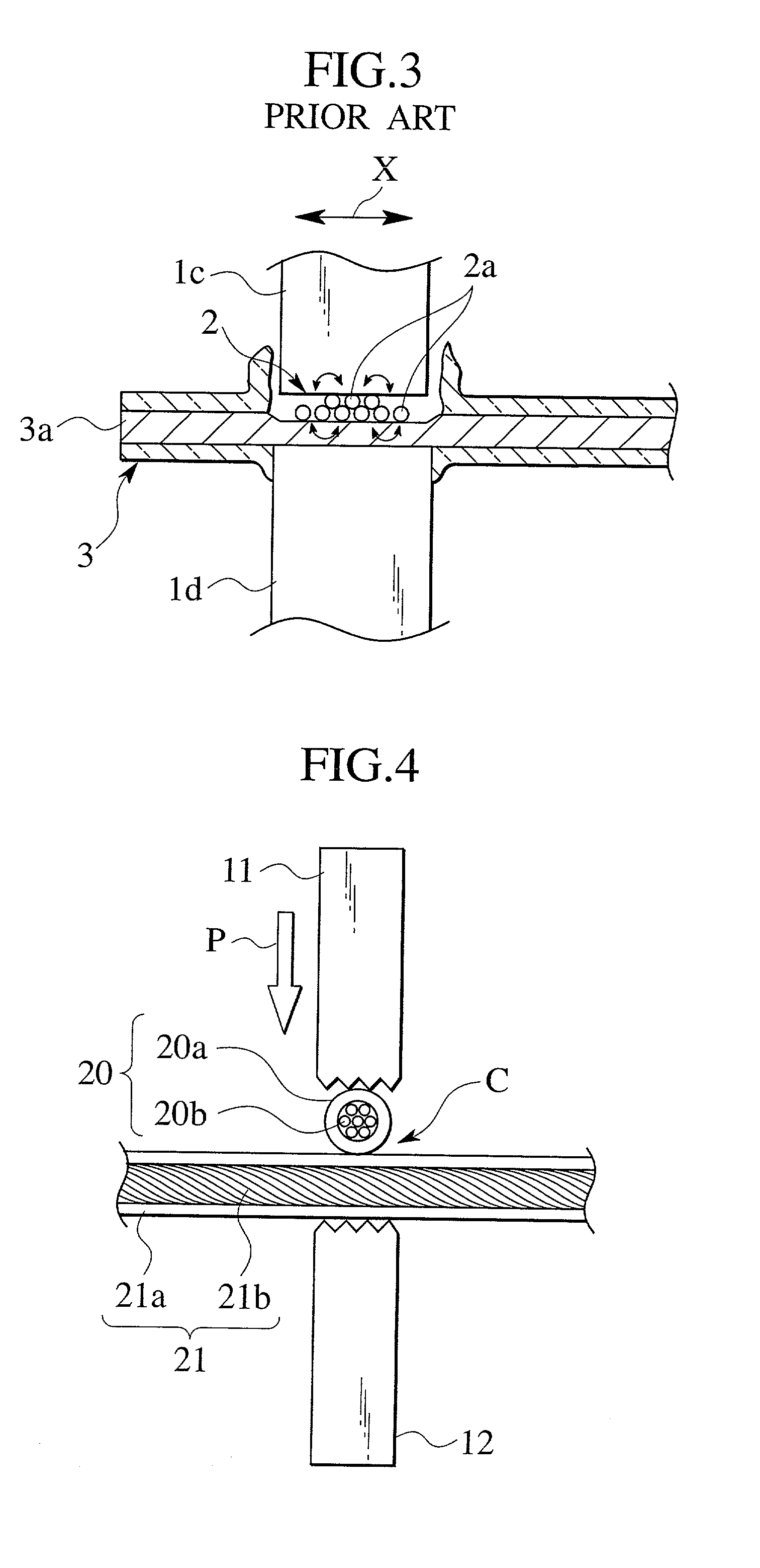
Thus, the vibration energy of the ultrasonic vibration adversely escapes as rotation of the conductor 2a, and the vibration energy can not be transmitted to a surface of the conductor, which deteriorates bonding effect.

Method used


Image

  • Ultrasonic bonding method of electric wires
  • Ultrasonic bonding method of electric wires
  • Ultrasonic bonding method of electric wires

Examples


Embodiment Construction

[0018] An embodiment of the present invention will be explained in detail with reference to the accompanying drawings.

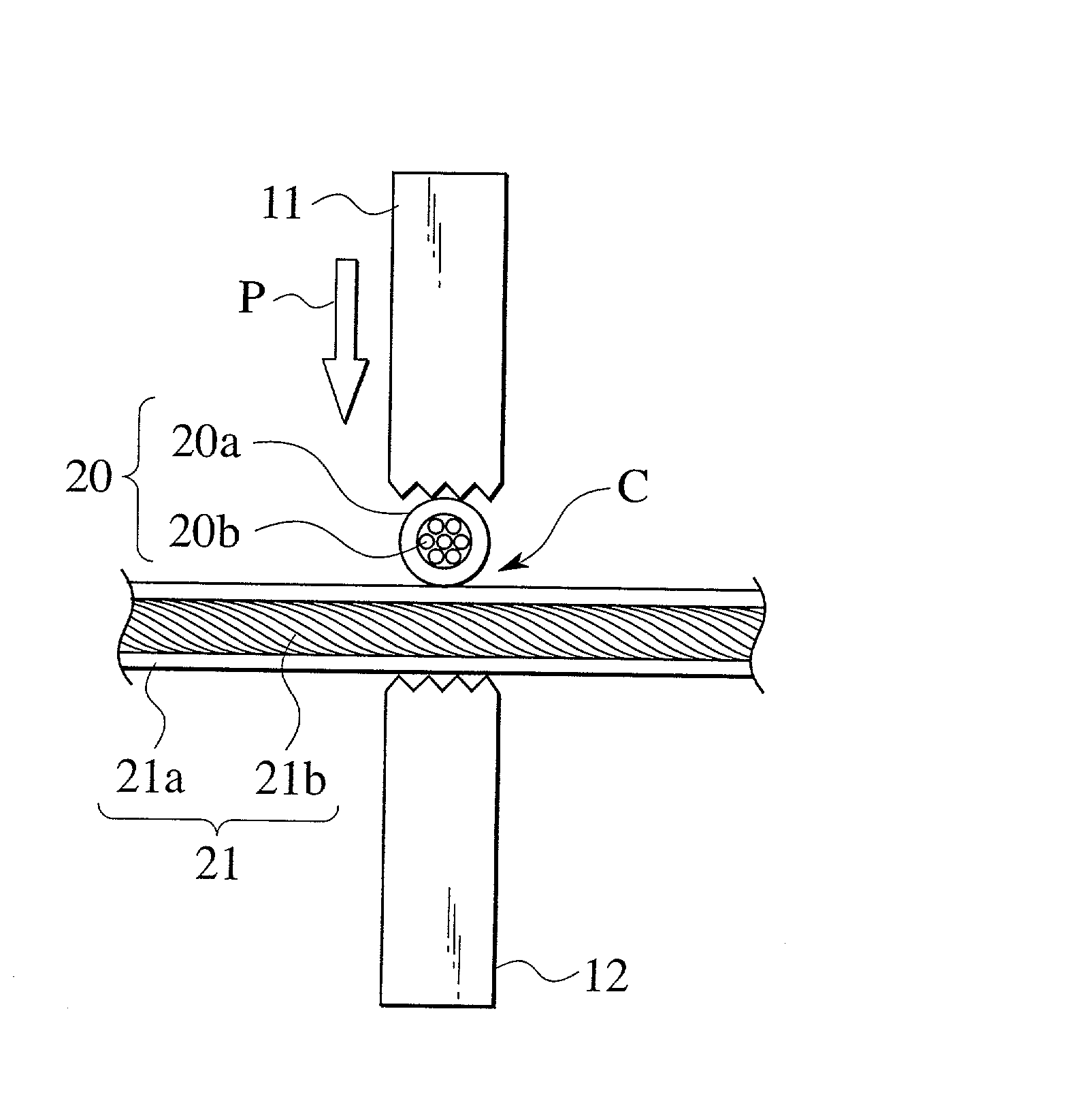
[0019] In an ultrasonic bonding method of electric wires according to the present embodiment, coated electric wires are used as electric wires. As shown in FIG. 4, a horn-side chip 11 and an anvil-side chip 12 are vertically disposed such as to be opposed to each other. Coated electric wires 20 and 21 to be connected are intersected with each other between the horn-side chip 11 and the anvil-side chip 12, and intersected portions C of the coated electric wires 20 and 21 are set. The horn-side chip 11 is vertically movable, and the anvil-side chip 12 is fixed. If the horn-side chip 11 is lowered, the intersected portions C of the coated electric wires 20 and 21 disposed between the chips 11 and 12 are sandwiched under an appropriate pressurizing force in a pressurizing direction P.

[0020] If the ultrasonic vibration is propagated from an oscillator (not shown) to the h...


PUM

PropertyMeasurementUnit
angleaaaaaaaaaa
pressurizing forceaaaaaaaaaa
vibration energyaaaaaaaaaa

Abstract

Electric wires (20) and (21) are intersected with each other at right angles such that the electric wires (20) and (21) are inclined with respect to the vibration direction of ultrasonic vibration through 45°, intersected portions (C) of the electric wires (20) and (21) are set between a horn-side chip (11) and an anvil-side chip (12) in a pressurized state, and ultrasonic vibration is input to the intersected portions (C), thereby bonding the electric wires (20) and (21) to each other.

Description

[0001] 1. Field of the Invention[0002] The present invention relates to an ultrasonic bonding method of electric wires in which electric wires to be bonded are intersected with each other, and intersected portions are bonded to each other by ultrasonic vibration.[0003] 2. Description of Related Art[0004] In an ultrasonic bonding of coated electric wires, the coated electric wires are subjected to ultrasonic vibration and pressurizing force at the same time, thereby bonding the wires to each other (see Japanese Patent Application Laid-open No. H7-212036). The electric wires can be bonded to each other using the ultrasonic bonding method (see Japanese Patent Application Laid-open No. H9-29445).[0005] FIG. 1 shows one example of an ultrasonic bonding apparatus 1. In the ultrasonic bonding apparatus 1, a horn 1b projects from an oscillator 1a in a horizontal direction, and a horn-side chip 1c is fixed to a tip end of the horn 1b. An anvil-side chip id is opposed to the horn-side chip 1c...

Claims


Application Information

Patent Timeline
Patent Type & Authority Applications(United States)
IPC IPC(8): B23K101/38H01R43/02B23K20/10
CPCB23K20/10B23K2201/38Y10T29/49201B23K2101/38
Inventor KONDO, MASAYUKI
Owner YAZAKI CORP
Learn More