Eureka AIR delivers breakthrough ideas for toughest innovation challenges, trusted by R&D personnel around the world.

Liquid-crystal device and a method of driving the same

a liquid crystal device and a technology of driving the same, applied in the direction of static indicating devices, non-linear optics, instruments, etc., can solve the problem of insufficient phase shi

Inactive Publication Date: 2002-06-06
STANLEY ELECTRIC CO LTD
View PDF7 Cites 15 Cited by
  • Summary
  • Abstract
  • Description
  • Claims
  • Application Information

AI Technical Summary

Benefits of technology

[0013] By using the liquid-crystal device technique, it is possible to remarkably change the characteristics of liquid crystal at a high speed.
[0014] In a liquid-crystal device according to the present invention, a high-speed switching operation and a remarkable change in optical characteristics of liquid crystal are compatible with each other. Performance of optical functional devices and phase modulating devices can be improved.

Problems solved by technology

However, the phase shift is insufficient.

Method used


Image

  • Liquid-crystal device and a method of driving the same
  • Liquid-crystal device and a method of driving the same
  • Liquid-crystal device and a method of driving the same

Examples


first embodiment

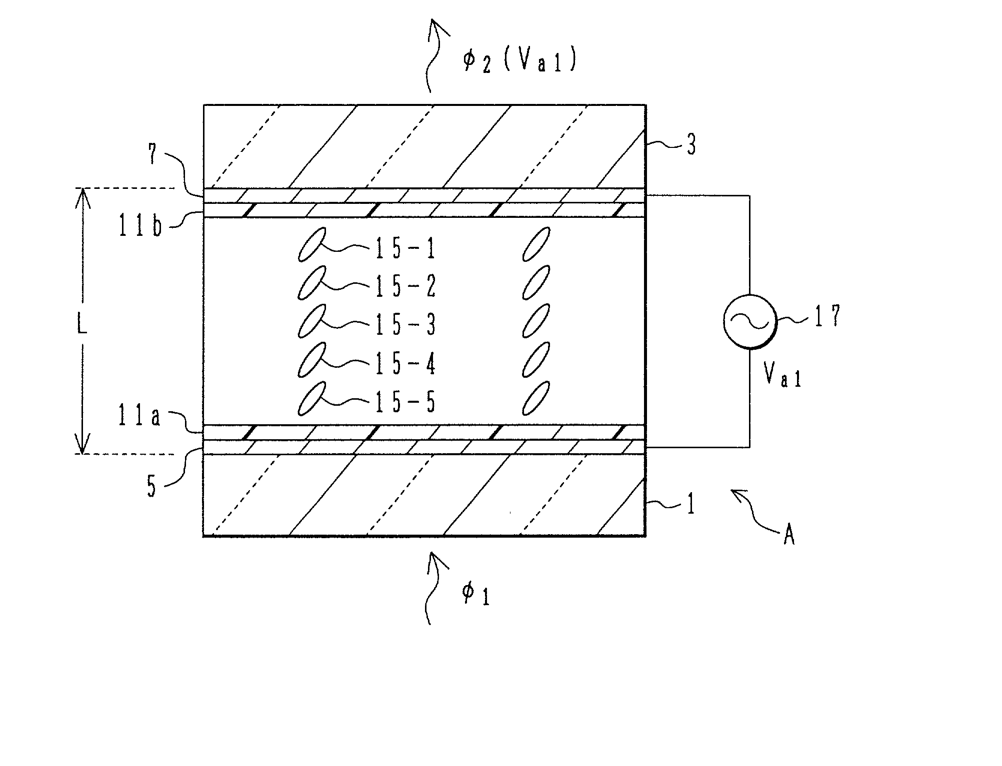
[0025] Referring now to FIGS. 1A, 1B, 2, and 3, description will be given of the present invention. As shown in FIGS. 1A and 1B, a liquid-crystal device A includes two transparent glass substrates 1 and 3 disposed in parallel with each other with a predetermined distance L therebetween, first and second transparent electrodes 5 and 7 formed respectively on inside surfaces of the respective substrates 1 and 3, and tolane liquid-crystal molecules 15 (15-1 to 15-5) interposed between the glass substrates 1 and 3.

[0026] Alignment layers 11a and 11b prepared to align the tolane liquid-crystal molecules 15 in an anti-parallel state are formed respectively on the first and second transparent electrodes 5 and 7. Materials for the tolane liquid-crystal molecules 15 are, for example, liquid-crystal materials of bicyclic alkylalkoxy tolane and tricyclic alkyl cyclohexyl alkoxy tolane. The materials have a large birefringence index and low viscosity, for example, the large birefringence index ....

second embodiment

[0065] Referring to FIG. 7, description will now be given of a first variation of the method of driving the liquid crystal device of the FIG. 7 shows a waveform of a driving voltage substantially equal to that of FIG. 4. The waveform of the driving voltage of FIG. 7 differs from that of FIG. 4 in that in zone III from when the voltage is turned off (the fourth voltage) to when a voltage (the second voltage) is applied again (zone IV), the applied voltage is gradually increased toward the second voltage Va2.

[0066] In the operation using the voltage waveform of FIG. 4, since the waveform of zone III is applied, the phase shift is possibly increased to a value higher than the desired value for the following reasons. The liquid-crystal molecules in the bulk react slowly and have not the desired inclination yet. Therefore, until the liquid-crystal molecules in the bulk are inclined to the desired state, the applied voltage is controlled as shown in zone III of FIG. 7. By gradually incre...


PUM

PropertyMeasurementUnit
voltageaaaaaaaaaa
distanceaaaaaaaaaa
voltagesaaaaaaaaaa

Abstract

A method of driving a liquid-crystal device having a gap of 15 mum to 200 mum between transparent substrates, a first electrode and a second electrode formed on opposing surfaces of the substrates, and liquid crystal filled in the gap between the substrates, the liquid crystal changing direction by applying a driving voltage, includes the steps of (a) applying a first waveform to obtain a first optical characteristic of the liquid crystal and (b) applying a second waveform to obtain a second optical characteristic of the liquid crystal other than the first optical characteristic, the second waveform having an effective voltage lower by 10 V to 500 V than an effective voltage of the first waveform.

Description

[0001] This application is based on Japanese Patent Application 2000-315567 filed on October 16th, all entire content of which is incorporated in this application by reference.[0002] 1. Field of the Invention[0003] The present invention relates to a liquid-crystal device and a method of driving the same, and in particular, to a liquid-crystal technique capable of remarkably changing a direction of alignment of molecules of liquid crystal at a high speed.[0004] 2. Description of the Related Art[0005] Liquid crystal has a refractive index of which the value changes in a director direction and a direction vertical or orthogonal thereto. For example, the director direction of liquid crystal can be controlled by changing a voltage applied thereto, and optical characteristics such as the refractive index can be changed by applying a voltage thereto. By using the functional properties of liquid crystal, it is possible to produce optical modulation devices such as a liquid-crystal lens, a l...

Claims


Application Information

Patent Timeline
Patent Type & Authority Applications(United States)
IPC IPC(8): G02F1/133G09G3/36
CPCG02F1/13306G09G2310/06G09G3/3622G02F2203/50
Inventor TOKO, YASUOIWAMOTO, YOSHIHISATAKESHIMA, KAZUKI
Owner STANLEY ELECTRIC CO LTD
Why Eureka
Eureka Blog
Learn More