
Fluid dispenser

a dispenser and fluid technology, applied in the field of biological reaction systems, can solve problems such as limited computer control

Inactive Publication Date: 2002-03-21
VENTANA MEDICAL SYST INC
View PDF32 Cites 24 Cited by
  • Summary
  • Abstract
  • Description
  • Claims
  • Application Information

AI Technical Summary

Benefits of technology

[0030] Another object of the invention is to provide an automated biological reaction system which provides for a means of automatically downloading data relating to the reagents including serial numbers, reagent types, lot numbers, expiration dates, dispenser type, and the like in an efficient and reliable manner.
[0031] Another object of the invention is to provide an automated biological reaction system which consistently and efficiently applies a predetermined amount of buffer upon the slide to which a precise volume of reagent can be added upon the slide.
[0032] A further object of the invention is to provide a fluid dispenser, which is used in conjunction with the biological reaction apparatus, which is reliable.
[0033] Yet a further object of the invention is to provide a fluid dispenser, which is used with a wider array of chemistries in conjunction with the biological reaction apparatus, which is easy to manufacture.
[0034] Still another object of the invention is to provide a fluid dispenser, which is used in conjunction with the biological reaction apparatus, which is compact in size.
[0035] Still yet another object of the invention is to provide a fluid dispenser which is easy to prime.

Problems solved by technology

However, the computer control is limited in that it is dedicated to and resident on the biological reaction apparatus.

Method used


Image

  • Fluid dispenser
  • Fluid dispenser
  • Fluid dispenser

Examples


Embodiment Construction

[0091] The automated immunostaining system of this invention performs all steps of immunohistochemical irrespective of complexity or their order, at the time and temperature, and in the environment needed. Specially prepared slides containing a bar code identifier and a mounted tissue section are placed in special supports on a carousel, subjected to a preprogrammed sequence of reactions, and are removed from the carousel, ready for examination. For purposes of clarity of the following description of the apparatus of this invention and not by way of limitation, the apparatus will be described in terms of immunohistochemical processes.

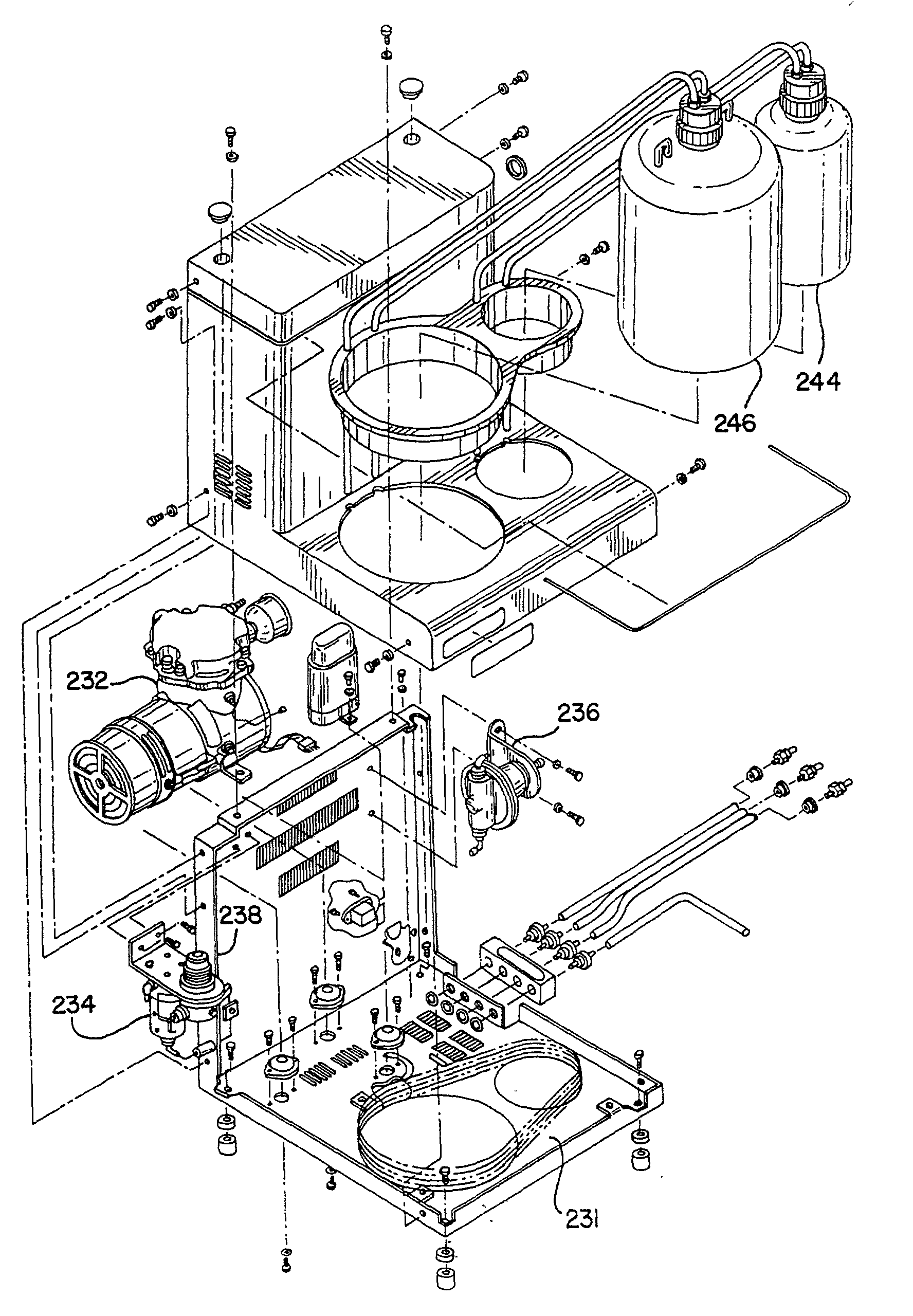
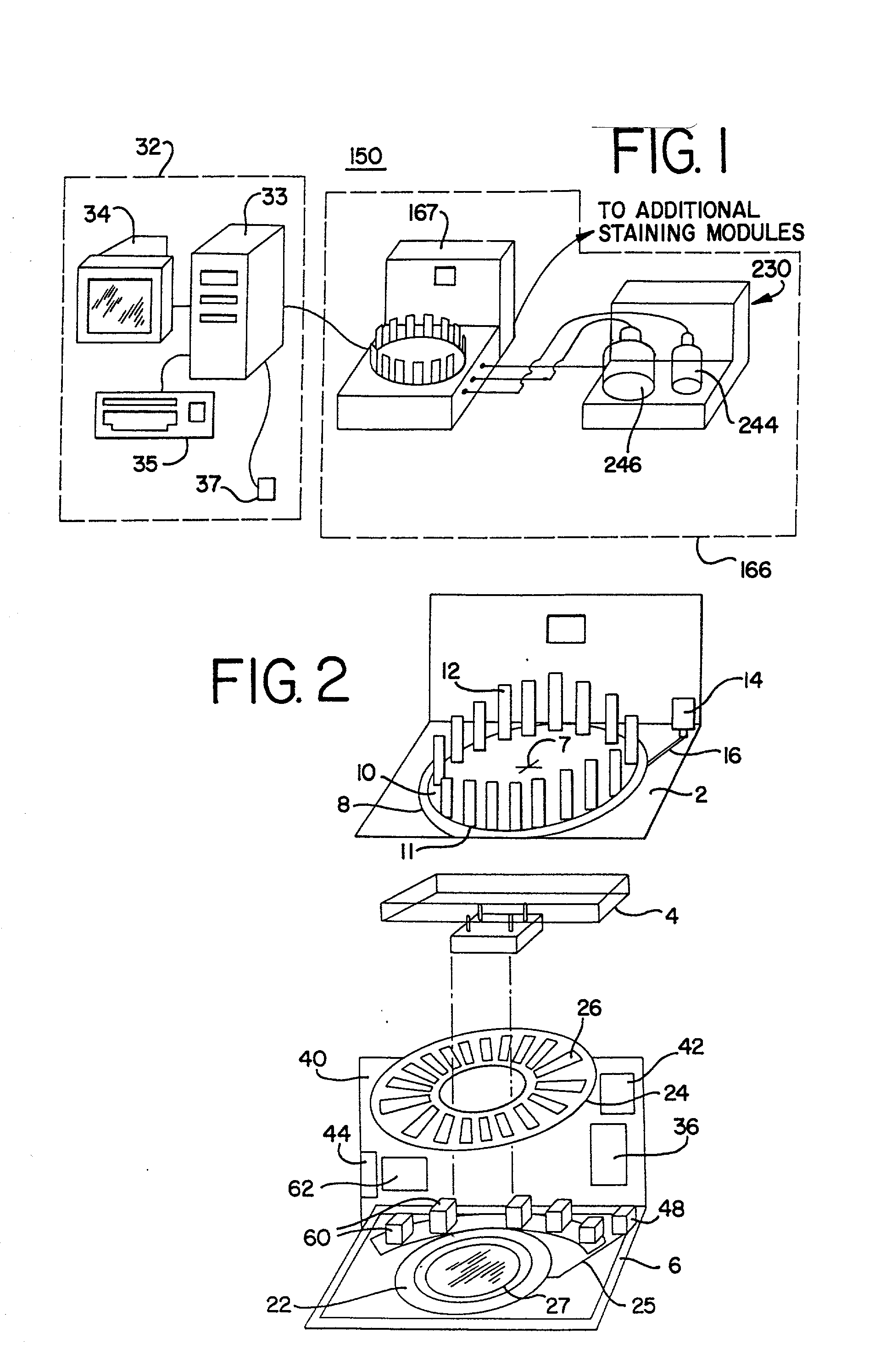
[0092] FIG. 1 is front right isometric view of the automated biological reaction system with a host device 32 and one remote device 166. The remote device 166 includes a staining module 167, bulk fluid module 230 and the host device 32 includes a host computer 33, a monitor 34, a keyboard 35 and a mouse 37. FIG. 2 is a front right isometric view of the ...


PUM

PropertyMeasurementUnit
angleaaaaaaaaaa
temperaturesaaaaaaaaaa
pressureaaaaaaaaaa

Abstract

A method and apparatus for an automated biological reaction system is provided. In the processing of a biological reaction system, there is a need for consistently placing an amount of fluid on a slide. In order to accomplish this, several methods are used including a consistency pulse and a volume adjust means. Moreover, in order to reliably operate an automated biological reaction system, the dispenser must be reliable, easy to assemble and accurate. Among other things, in order to accomplish this, the dispense chamber is substantially in line with the reservoir chamber, the reservoir chamber piston is removed, and the flow of fluid through the dispenser is simplified. Further, in order to operate the automated biological reaction system more reliably, the system is designed in modular pieces with higher functions performed by a host device and the execution of the staining operations performed by remote devices. Also, to reliably catalog data which is used by the automated biological reaction system, data is loaded to a memory device, which in turn is used by the operator to update the operator's databases. The generation of the sequence of steps for the automated biological reaction device based on data loaded by the operator, including checks to determine the ability to complete the run, is provided.

Description

[0001] This application is a continuation-in-part application to U.S. patent application Ser. No. 08 / 909,335 (pending) filed on Aug. 11, 1997.NOTICE REGARDING COPYRIGHT[0002] A portion of the disclosure of this patent document contains matter subject to copyright protection. The copyright owner has no objection to the facsimile reproduction by anyone of the patent disclosure document as it appears in the Patent and Trademark Office files and records but otherwise retains all copyrights whatsoever.[0003] A. Field of the Invention[0004] This invention relates to biological reaction systems, and more particularly relates to a method and apparatus for an automated biological reaction system.[0005] B. Description of Related Art[0006] Immunostaining and in situ DNA analysis are useful tools in histological diagnosis and the study of tissue morphology. Immunostaining relies on the specific binding affinity of antibodies with epitopes in tissue samples, and the increasing availability of an...

Claims


Application Information

Patent Timeline
Patent Type & Authority Applications(United States)
IPC IPC(8): G01N1/00A47K5/12B67D7/06G01N1/30G01N1/31G01N35/00G01N35/10
CPCG01N1/312G01N35/00871G01N35/1002G01N35/1016Y10T436/2575G01N2035/00881G01N2035/1034Y10T436/11Y10T436/112499G01N2001/317Y10T137/7873
Inventor FORD, ANTHONYMCDANIEL, DARINMEAD, STEPHENRICHARDS, WILLIAMSHOWALTER, WAYNEDRUYOR-SANCHEZ, BOBBIHEILMAN, BRONWENMCGRAW, BRIAN
Owner VENTANA MEDICAL SYST INC
Learn More