
Charger assembly

a technology of charging assembly and charging device, which is applied in the direction of electrochemical generators, secondary cell servicing/maintenance, transportation and packaging, etc., can solve the problems of not adequately preventing such overcharging or relying on the user, failing to adequately, and charging assembly not adequately providing such a "float charge"

Inactive Publication Date: 2002-01-03
HABA CHAZ G
View PDF0 Cites 47 Cited by
  • Summary
  • Abstract
  • Description
  • Claims
  • Application Information

AI Technical Summary

Benefits of technology

[0009] It is a second object of the present invention to provide a charger assembly which overcomes some or all of the previously delineated drawbacks of prior charger assemblies and which substantially reduces the likelihood of overcharging a battery assembly while allowing the battery assembly to be substantially, fully, and electrically charged.
[0010] It is a third object of the present invention to provide a charger assembly which overcomes some or all of the previously delineated drawbacks of prior charger assemblies and which further and selectively provides a "trickle charge" to a battery assembly, thereby substantially preventing discharge of the battery assembly during non-use.
[0011] It is a fourth object of the present invention to provide a charger assembly which overcomes the various and previously delineated drawbacks of prior charger assemblies and which selectively and periodically communicates electrical charge to a battery assembly while being relatively inexpensive, lightweight, uncomplicated, and relatively compact.
[0016] According to a fourth aspect of the present invention a charger assembly is provided, and communicates voltage to a battery assembly, the voltage being dynamically modified to substantially prevent overcharging of the battery assembly.

Problems solved by technology

While many chargers do allow a battery assembly to be fully charged, they do not adequately prevent such overcharging or rely upon the user or the operator to determine whether a complete charge has been communicated to the battery assembly.
These prior charges therefore fail to adequately ensure that such a complete charge has been communicated to the battery assembly while concomitantly and substantially preventing such undesirable overcharging.
Many prior charge assemblies do not adequately provide such a "float charge" and / or do not allow the selective use of such trickle charge or automatic "recharge" functionality.
Prior chargers do not typically operate with a wide variety of received and diverse voltages, currents, and / or electrical power and do not typically and automatically recognize such received voltages, currents, and power.
Rather, these prior chargers require the operator to recognize the type and / or value of these received voltages, currents, and power and provide this information to the charger or to simply "not use" the charger with such improper input signals, thereby increasing the likelihood of operator error or operator induced malfunction and undesirably increasing the complexity of the overall electrical charging process.

Method used


Image

  • Charger assembly

Examples


Embodiment Construction

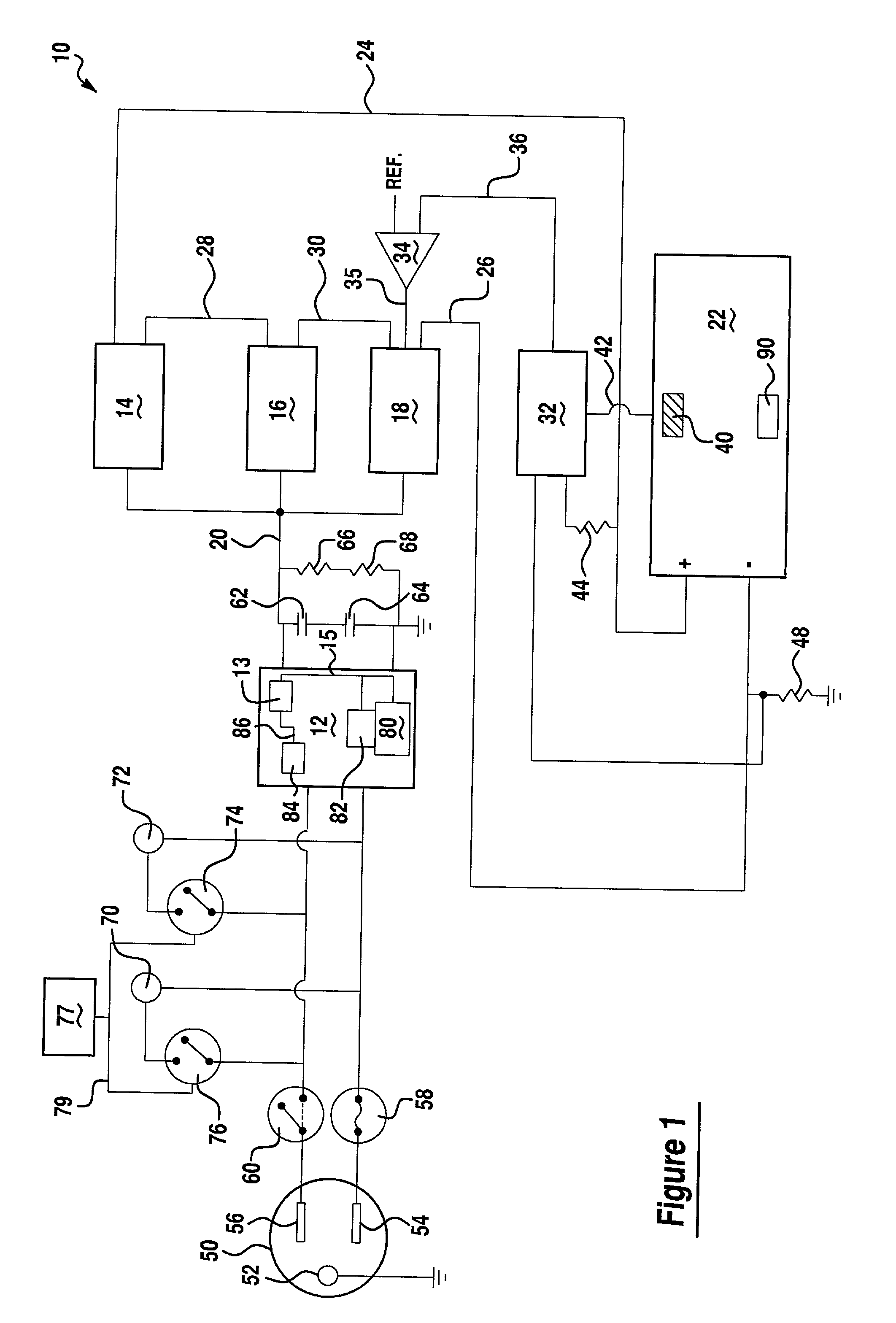
[0019] Referring now to FIG. 1, there is shown a charger assembly 10 which is made in accordance with the teachings of the preferred embodiment of the invention. As shown, charger assembly 10 includes an input module 12 which may, in one non-limiting embodiment, include a processor 13 operating under stored program control, and substantially identical direct current to direct current converters 14, 16, and 18 which are physically and communicatively coupled to the input module by bus 20. Converter 14 is selectively, removably, physically, and communicatively coupled to the positive terminal of the battery assembly 22 by use of bus 24 and converter 18 is selectively, removably, physically, and communicatively coupled to the negative terminal of the battery assembly 22 by bus 26. Converter 14 is selectively, removably, physically and communicatively coupled to converter 16 by use of bus 28 and converter 16 is selectively, removably, physically, and communicatively coupled to the conve...


PUM

PropertyMeasurementUnit
voltageaaaaaaaaaa
resistanceaaaaaaaaaa
root mean square voltageaaaaaaaaaa

Abstract

A charger assembly 10 for use with a battery assembly 22. Charger assembly 10 includes a member 50 which is selectively and removably insertable into a conventional electrical power outlet, effective to allow electrical power to be communicated to the charger assembly 10. The communicated electrical power is selectively transferred to the battery assembly 22, effective to substantially and fully charge the battery assembly 22 in a manner which substantially reduces the likelihood of overcharging and in a manner which selectively allows a "float" voltage or "trickle charge" to be provided to the battery assembly 22.

Description

(1) FIELD OF THE INVENTION[0001] This invention relates to a charger assembly and more particularly to an assembly which selectively communicates electrical power to a battery assembly effective to electrically charge the battery assembly.(2) BACKGROUND OF THE INVENTION[0002] Charger assemblies are generally used to allow electrical power to be communicated from an electrical power source to a battery assembly (i.e. one or more batteries), effective to allow the battery assembly to be electrically charged and to thereafter allow the charged battery assembly to provide the stored charge and power to many diverse types of devices and apparatuses in order to allow these devices and apparatuses to operate.[0003] While it is desirable to fully and completely charge such a battery assembly, it is concomitantly and also highly desirable to substantially and automatically ensure that the battery assembly is not overcharged (i.e. that the battery assembly does not receive a voltage and / or an...

Claims


Application Information

Patent Timeline
Patent Type & Authority Applications(United States)
IPC IPC(8): H01MH01M10/42H01M10/44H01M10/46H02J7/00H02J7/04
CPCH01M10/42H01M10/44H01M10/46H02J7/0073H02J7/04H02J7/0071Y02E60/10
Inventor HABA, CHAZ G
Owner HABA CHAZ G
Learn More