
Tool device and method for measuring a condition of a machining tool

a technology for measuring tools and machining tools, which is applied in the direction of manufacturing tools, grinding machine components, metal-working machine components, etc., can solve the problems of tool wear, tool wear, and machining tools always end up with some kind of wear and tear

Active Publication Date: 2022-11-01
AGATHON MASCHFAB
View PDF8 Cites 0 Cited by
  • Summary
  • Abstract
  • Description
  • Claims
  • Application Information

AI Technical Summary

Benefits of technology

[0016]In one embodiment the fiber optic sensor is an interferometric fiber optic sensor. The interferometric fiber optic sensor uses an interference between two light beams that are propagated through different optical paths provided by a single optical fiber or two different optical fibers. Such interferometric fiber optic sensor with optical fibers offering advantages such as easy multiplexing, mechanical flexibility and low-cost sensor base material. Optical fibers have been widely deployed owing to their good light guidance performance and other unique characteristics such as high sensitivity, low fabrication cost, small form factor, high accuracy.
[0027]Furthermore, the method of the invention has the potential for the detection of numerous process and state variables that may be relevant for the machining operation, for example a grinding performance. The method can be used to determine an amount of wear of the surface of the tool device, dressing condition of the tool device, thickness of lubrication film, distance between workpiece and tool device and / or built-up edge of the tool device. For example the built-up edge can be seen as an accumulation of material against a rake face of a cutting tool which changes tool geometry and rake steepness. The benefits of fiber optic sensors are their small size, no electrical requirements at the point of measurement and a certain stability. The sensitivity of optical fibers is based on wavelength encoded qualities of interest which can transmitted without loss of fidelity over the length of fiber. Therefore, the tool device comprising multiple embedded optical fibers can be used to provide a system in which various information are directly and accurately recorded like heat generation, temperature and coolant layer.
[0029]To aim to maximize the production rate while maintaining specific product quality frame and to reduce the cost and time of the production simultaneously the topography of the real tool such as a grinding wheel or a cutting tool must be measured and analyzed to generate at least information useful for the dressing of the tool device. In one embodiment according to the invention the grinding wheel including the fiber optic sensor embedded provides grinding under optimum grinding condition without a complex system of different and independent sensors associated to the grinding machine.

Problems solved by technology

In machining processes using machining tools always end up with some kind of wear on them due to cutting action between workpiece and a or multiple tool edges.
In particular, the tool wear can be described as a change of shape of the tool from its original shape during cutting or grinding resulting from gradual loss of tool material or deformation.
Generally, measurements can only be done between machining runs because the area of wear of the tool is not visible during actual machining.
Indirect sensors can only estimate the wear as they have no direct way to measure the actual wear but they rely on secondary effects of the wear.
But there is a disadvantage that the accuracy of such measurements are impaired by thermal effects and by effects resulting from the atmosphere in the contact area in particular due to the circulating coolant.
During the grinding process mechanical, chemical and thermal loads are applied to the grinding wheel resulting in wear and in a large amount of frictional heat introducing plastic deformation, undesirable changes in the microstructure and residual stress state of the material of the workpiece.
Conventionally, the grinding result and the condition of the grinding wheel are only checked after completion of the grinding process or periodically during the grinding process at intervals causing loss of productivity.
But still unknown is to determine the exact moment to accomplish the dressing process is a problem without a precise solution.
This makes it infeasible for industrial applications where an enormous variety of different workpiece, tool and machine combinations with unknown properties are used.
But in general the disadvantage of external mounted laser displacement sensors is that the influence of cooling lubricant is great as well as thermal and mechanical deviations of the machine cause displacement between the laser sensor and the wheel or tool.

Method used


Image

  • Tool device and method for measuring a condition of a machining tool
  • Tool device and method for measuring a condition of a machining tool
  • Tool device and method for measuring a condition of a machining tool

Examples


Embodiment Construction

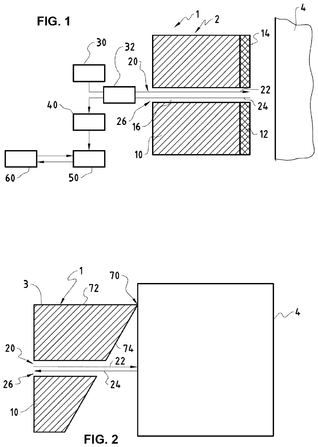
[0038]In FIG. 1, the tool device 1 can be seen in a cross section view as well as a workpiece 4. Shown in FIG. 1 is a grinding tool 2 such as a grinding wheel 2 comprising a base body 10 and an abrasive layer 12, consisting of a compound in which abrasive grains are embedded. The compound is of bonding material and is composed for example of metal alloy, of synthetic resin or of ceramic. Embedded in a known way in this bonding material are abrasive grains which can be made of diamond or another correspondingly suitable material. As can been seen from FIG. 1 embedded into the base body 10 are a fiber optic sensor 20, providing two optical paths, in particular a first optical path 22 and a second optical path 24, preferably provided as in-line structure offering two optical paths in one physical line, called fiber 26 to direct light beams emitted by a light source 30. The fiber optic sensor 20 is fabricated from low-cost base material, typically silica and can be used in harsh conditi...


PUM


Abstract

A tool device (1) for machining a workpiece (4) by cutting, milling, drilling or grinding, comprising a sensor (20) for detecting a condition of the tool device (1) during machining, wherein the sensor (20) is connectable to a receiving unit (40), which transmits data to an analysis unit (50) for analyzing the received data. The sensor (20) is configured as a fiber optic sensor (20) comprising at least one optical fiber (26) providing an incident optical path (22) and a reflected optical path (24) for a light beam emitted by a connectable light source (30) and with a distal end thereof lying in a surface (14, 74) of the tool device (1) such that the optical path length can be measured.

Description

TECHNICAL FIELD[0001]The present invention relates to a tool device and a method capable of measuring a condition of a machining tool such as grinding tool and / or cutting tool during a machining process. The present invention is focused to measure tool wear.BACKGROUND OF THE INVENTION[0002]In machining processes using machining tools always end up with some kind of wear on them due to cutting action between workpiece and a or multiple tool edges. In particular machining tools influence the productivity and the economy of the machining operation and the quality of the machined products. Many attempts have been made to implement an automatic system to measure tool wear which removes the need for manual inspection and minimizes the time used on wear measurement. Several different methods have been developed to monitor the condition of tools, such as cutting inserts for cutting, milling or drilling or grinding tools, i.e. exchangeable and / or indexable inserts and to predict the tool wea...

Claims


Application Information

Patent Timeline
Patent Type & Authority Patents(United States)
IPC IPC(8): B23Q17/24B23Q17/09B24B49/02B24B49/12
CPCB23Q17/2457B23Q17/0952B23Q17/2495B24B49/02B24B49/12B23Q17/0957B23Q17/2233
Inventor SCHOLZE, STEPHANMAIER, MARKUSWEISS, LUKAS
Owner AGATHON MASCHFAB
Learn More