
System and methods for electric discharge machining

a technology of electric discharge machining and electric discharge, which is applied in the direction of logic circuits, metal-working apparatuses, pulse techniques, etc., can solve the problems of low material removal rate of known edm machining systems, slow machining process speed, and no discharge possibility

Active Publication Date: 2022-10-25
GENERAL ELECTRIC CO
View PDF24 Cites 0 Cited by
  • Summary
  • Abstract
  • Description
  • Claims
  • Application Information

AI Technical Summary

Problems solved by technology

However, at least some known EDM machining systems have low material removal rates due, in part, to a limitation that only one pulse can be generated at a time.
As a result, even though multiple electrodes may be used in some EDM systems, they have little to no possibility to discharge at the same time because they share the same control signal and the electrode connections are not electrically isolated from each other.
This leads to a slow machining process speed.

Method used


Image

  • System and methods for electric discharge machining
  • System and methods for electric discharge machining
  • System and methods for electric discharge machining

Examples


Embodiment Construction

[0013]In the following specification and the claims, reference will be made to a number of terms, which shall be defined to have the following meanings.

[0014]The singular forms “a”, “an”, and “the” include plural references unless the context clearly dictates otherwise.

[0015]Approximating language, as used herein throughout the specification and claims, is applied to modify any quantitative representation that could permissibly vary without resulting in a change in the basic function to which it is related. Accordingly, a value modified by a term or terms, such as “about”, “approximately”, and “substantially”, are not to be limited to the precise value specified. In at least some instances, the approximating language may correspond to the precision of an instrument for measuring the value. Here and throughout the specification and claims, range limitations are combined and interchanged; such ranges are identified and include all the sub-ranges contained therein unless context or lan...


PUM

PropertyMeasurementUnit
voltageaaaaaaaaaa
DC electric poweraaaaaaaaaa
electric chargeaaaaaaaaaa

Abstract

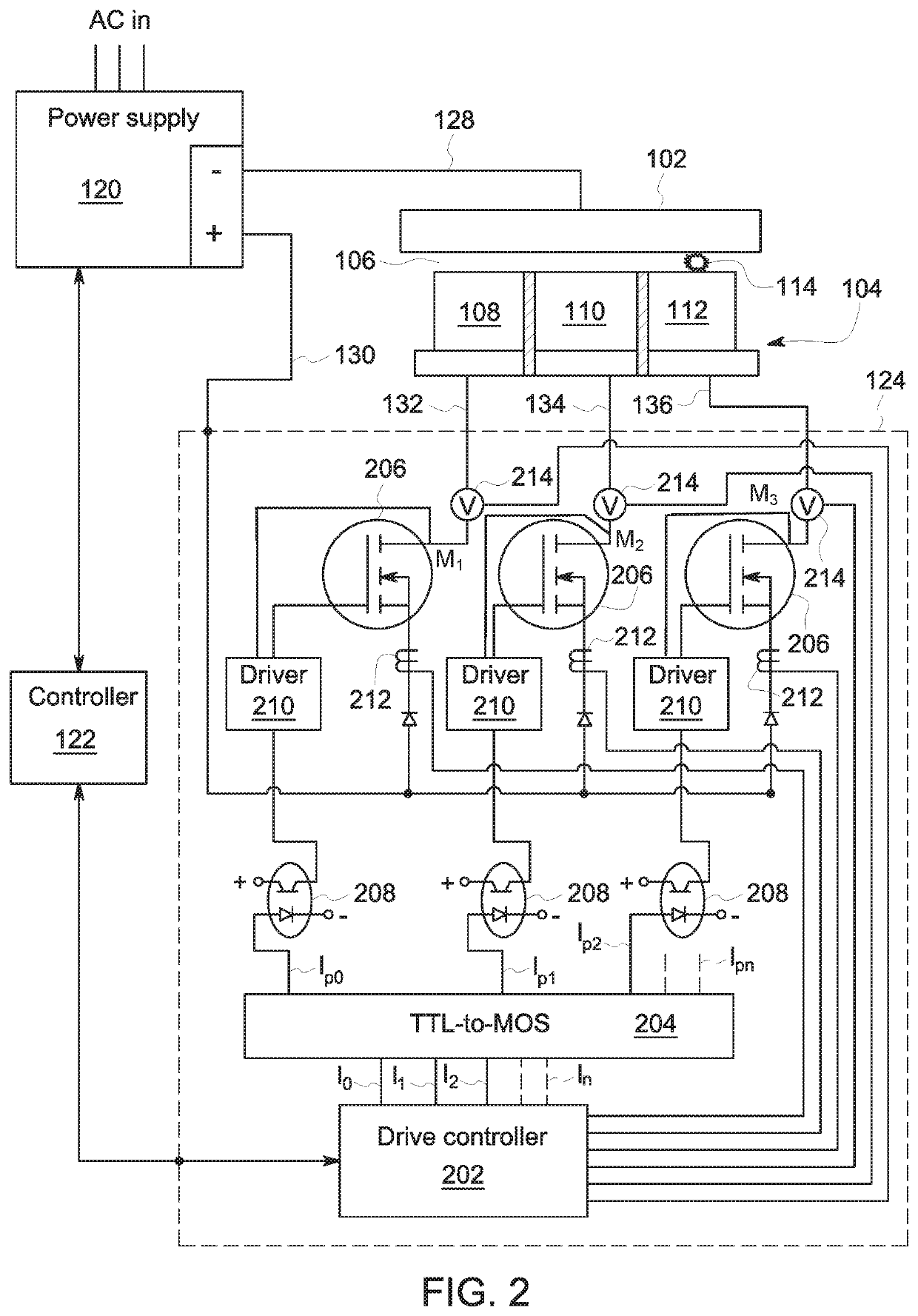
A multi-loop controller component for an electric discharge machining (EDM) system includes a plurality of power loop circuits coupled to an output of a power supply of the EDM system and configured to receive DC electric power from the power supply. Each power loop circuits electrically-isolated from other power loop circuits. The multi-loop controller component also includes a plurality of transistors. Each transistor is coupled to a respective power loop circuit and is configured to switch between an ON state and an OFF state to generate a pulse of the DC electric power through the respective power loop circuit. In addition, the multi-loop controller component has a drive controller coupled to the plurality of transistors. The drive controller is configured to transmit at least one control signal to at least one of the transistors to facilitate switching the transistor between the ON state and the OFF state.

Description

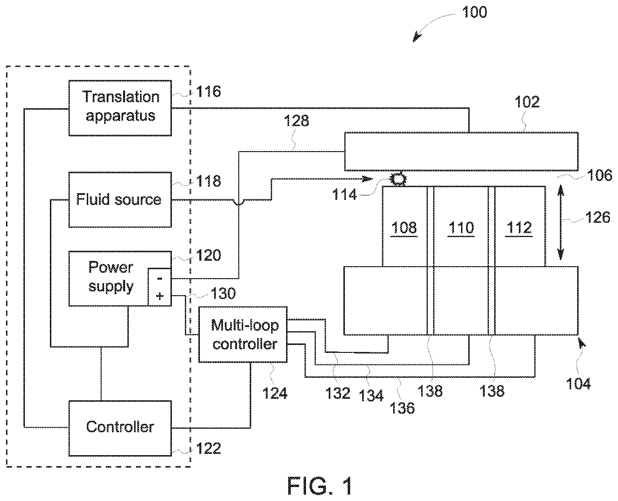
BACKGROUND[0001]The present disclosure relates generally to electric discharge machining (EDM) and, more particularly, to a multi-loop controller component for EDM systems and methods of machining therewith.[0002]EDM machining is typically used to fabricate a variety of difficult structures in difficult to machine materials. In at least some known EDM machining operations, a workpiece is placed into a tank of fluid, such as hydrocarbon-based oil. An electrode having, for example, a mirror image of the desired component or a cavity shape of the desired cavity in a component, is moved by a ram in proximity to the workpiece. An electric pulse is then applied to the gap between the electrode and the workpiece to generate electric discharges that facilitate removing material from the workpiece. However, at least some known EDM machining systems have low material removal rates due, in part, to a limitation that only one pulse can be generated at a time. As a result, even though multiple e...

Claims


Application Information

Patent Timeline
Patent Type & Authority Patents(United States)
IPC IPC(8): H03K19/0944B23H1/02
CPCH03K19/0944B23H1/028
Inventor LUO, YUANFENGLUO, YUEFENGLOMBARDO, DALE ROBERTHAYASHI, STEVEN ROBERT
Owner GENERAL ELECTRIC CO
Learn More