Stack frame
a technology of mounting holes and brackets, applied in the field of brackets, can solve the problems of difficult to ensure the fixing strength of the battery stack, difficult to provide the plurality of mounting holes to only one of the molded products, and large vibration, so as to reduce the force applied to the mounting holes, ensure the fixing strength, and ensure the fixing strength
- Summary
- Abstract
- Description
- Claims
- Application Information
AI Technical Summary
Benefits of technology
Problems solved by technology
Method used
Image
Examples
first embodiment
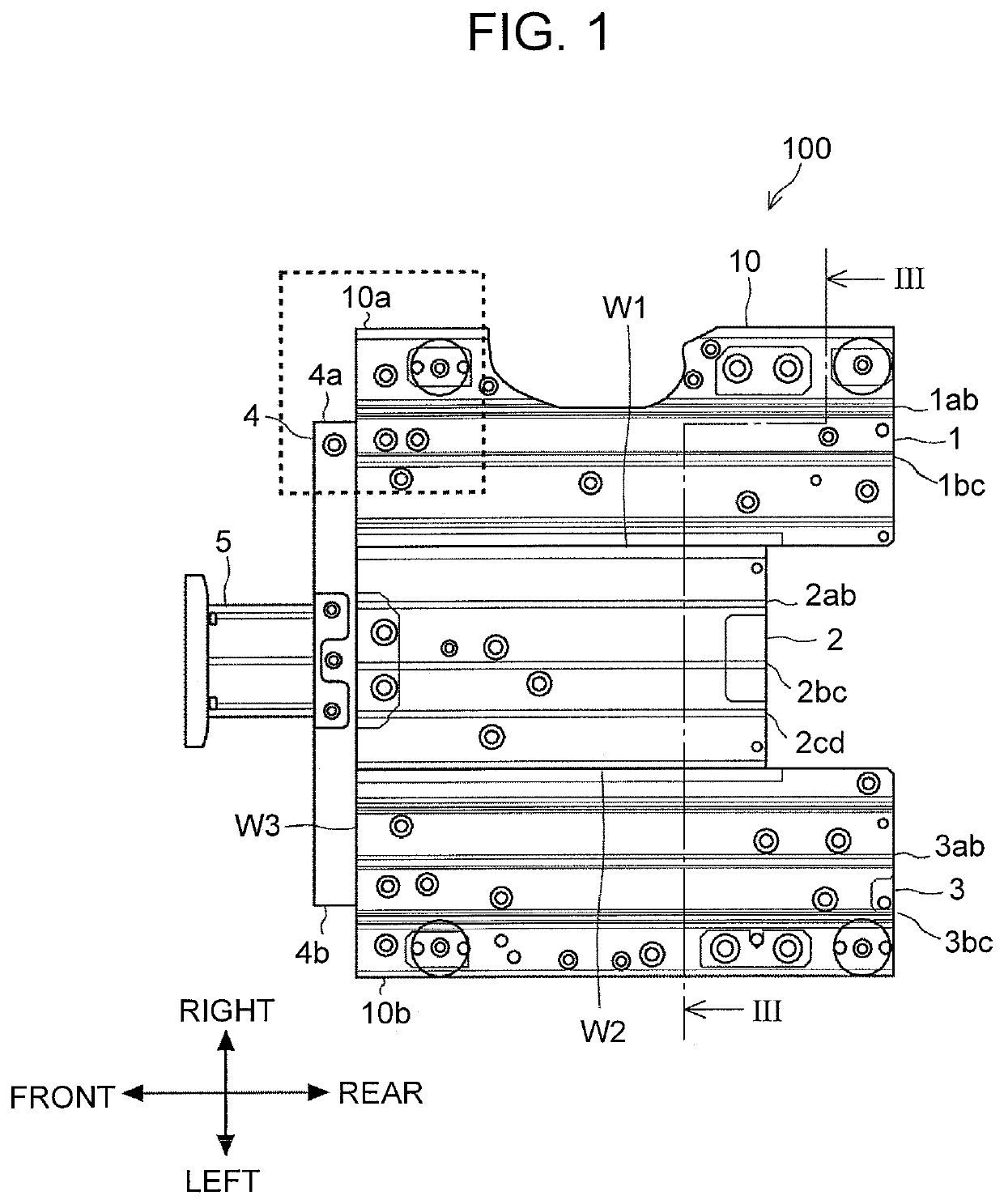
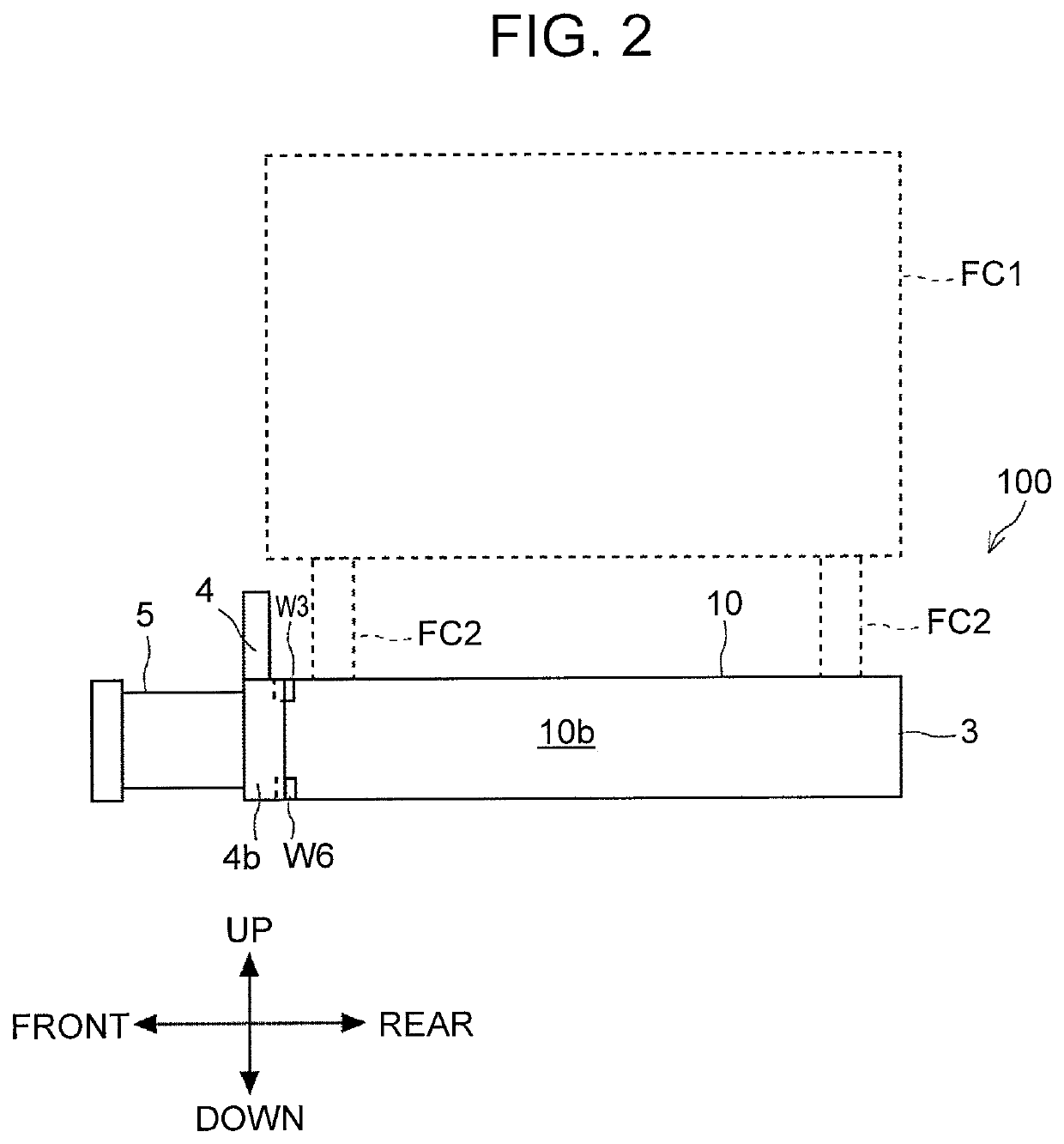
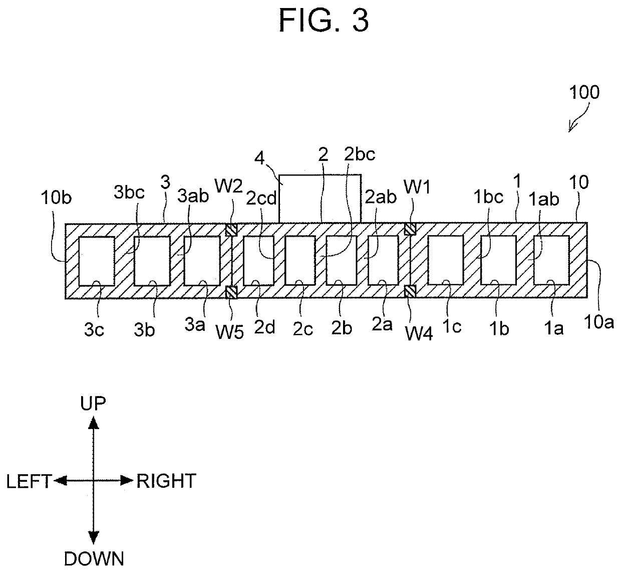
[0024]A stack frame according to the first embodiment will be described with reference to FIG. 1 to FIG. 4. FIG. 1 is a top view of the stack frame according to the first embodiment. FIG. 2 is a left side view showing the stack frame according to the first embodiment. FIG. 3 is a sectional view showing the stack frame according to the first embodiment. FIG. 4 is an enlarged view of an upper surface of the stack frame according to the first embodiment.
[0025]As a matter of course, three-dimensional orthogonal coordinates shown in FIG. 1 and the other drawings indicate the up-down direction, the right-left direction, and the front-rear direction, respectively, and they are used for convenient for explaining the positional relationship of components. FIG. 1 is a view of the stack frame 100 as viewed from above the stack frame 100. FIG. 2 is a view of the stack frame 100 shown in FIG. 1 as viewed from the left side the stack frame 100. FIG. 3 shows a cross-section of the stack frame 100 ...
example of modification
[0051]There is a stack frame 100a shown in FIG. 5. FIG. 5 is an enlarged view of an upper surface of an example of a modification of the stack frame according to the first embodiment. The stack frame 100a is an example of the modification of the stack frame 100 shown in FIG. 1 to FIG. 4. The stack frame 100a has the same configuration as that of the stack frame 100 except for the positions of the mounting holes FH1, FH2, FH3.
[0052]As shown in FIG. 5, the mounting holes FH1a, FH2a, FH3a are located at different locations from the mounting holes FH1, FH2, FH3 of the stack frame 100 shown in FIG. 4, respectively. Specifically, the mounting hole FH1a is located closer to the right end 10a of the main body 10 than the mounting hole FH1 is. The mounting hole FH2a is located at a position more leftward than the mounting hole FH2. The mounting hole FH3a is located closer to the right end 10a of the main body 10 than the mounting hole FH3 is. However, similarly, the mounting holes FH2a, FH3a...
second embodiment
[0056]A stack frame according to the second embodiment will be described with reference to FIG. 6. FIG. 6 is an enlarged view of an upper surface of a stack frame according to the second embodiment. The stack frame according to the second embodiment has the same configuration as those of the stack frames 100, 100a except for the positions and the number of the mounting hole FH1 and others.
[0057]As shown in FIG. 6, the stack frame 200 includes mounting holes FH21, FH22, FH23, FH24. The mounting holes FH21, FH22, FH23 are located at different locations from those of the mounting holes FH1, FH2, FH3 of the stack frame 100 shown in FIG. 4. The mounting hole FH21 is located more leftward than the mounting hole FH1. The mounting hole FH22 is located more leftward than the mounting hole FH2. The mounting hole FH23 is located more leftward in the main body 10 than the mounting hole FH3.
[0058]The mounting holes FH22, FH23 are disposed in the end surface covered region 11, and the mounting ho...
PUM
| Property | Measurement | Unit |
|---|---|---|
| length | aaaaa | aaaaa |
| width | aaaaa | aaaaa |
| gravity | aaaaa | aaaaa |
Abstract
Description
Claims
Application Information
 - R&D
- Intellectual Property
- Life Sciences
- Materials
- Tech Scout
- Unparalleled Data Quality
- Higher Quality Content
- 60% Fewer Hallucinations
Browse by: Latest US Patents, China's latest patents, Technical Efficacy Thesaurus, Application Domain, Technology Topic, Popular Technical Reports.
© 2025 PatSnap. All rights reserved.Legal|Privacy policy|Modern Slavery Act Transparency Statement|Sitemap|About US| Contact US: help@patsnap.com


