
Ducted double-magnetic-circuit coreless motor special for electric aircraft

a technology of electric aircraft and coreless motors, applied in the field of motors, can solve the problems of weakening the magnetic force lines that induce electromagnetic torque relative to the permanent magnet rotors

Active Publication Date: 2022-10-04
LU JIRONG
View PDF7 Cites 1 Cited by
  • Summary
  • Abstract
  • Description
  • Claims
  • Application Information

AI Technical Summary

Benefits of technology

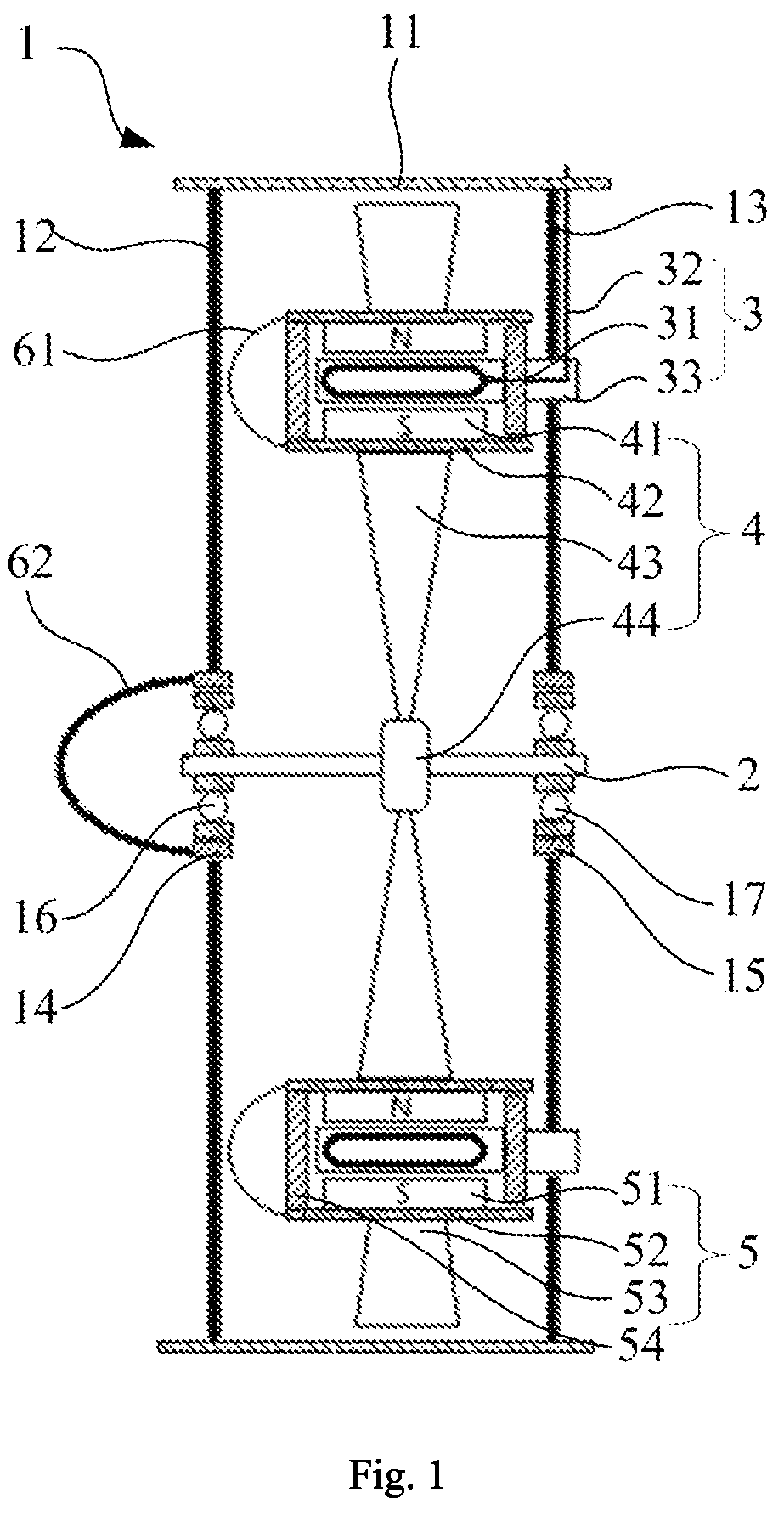
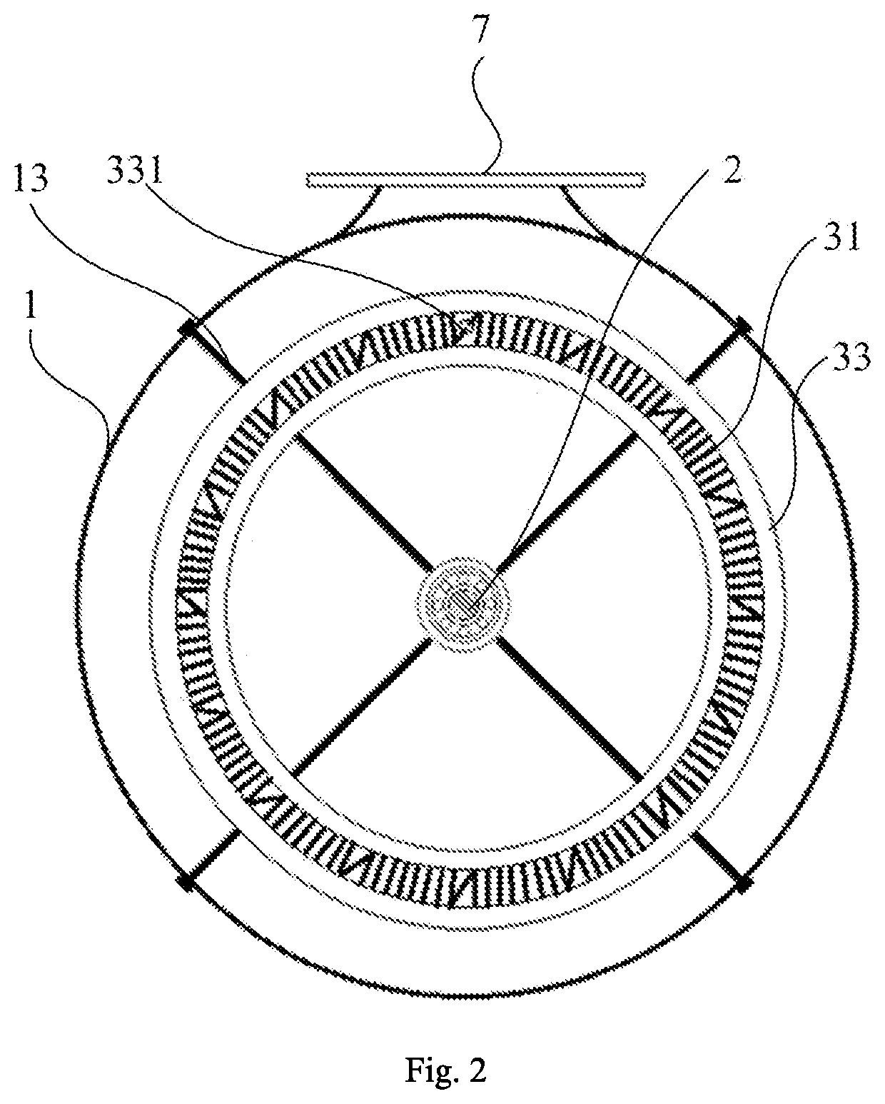
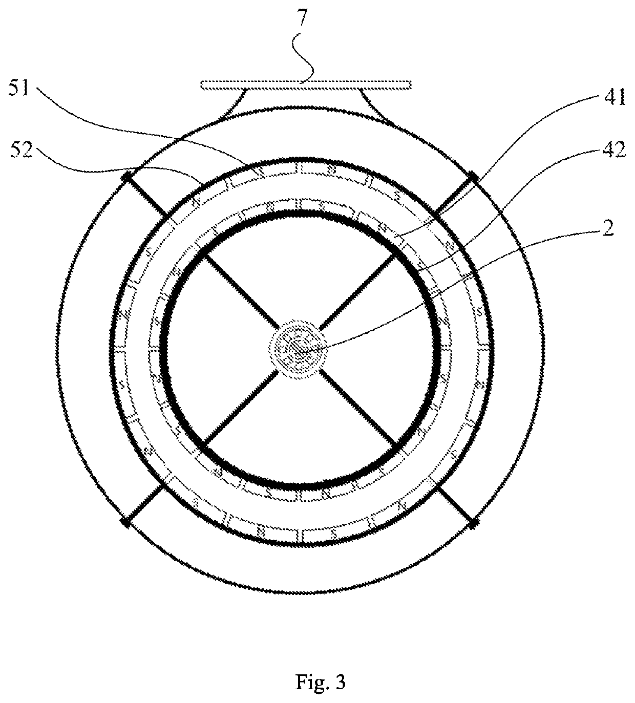
[0008]The coreless stator winding is arranged between the inner rotor structure and the outer rotor structure, and can generate an electromagnetic torque when current is applied, so that the inner rotor structure and the outer rotor structure can induce the electromagnetic torque of the coreless stator winding simultaneously, thereby generating a driving force for rotating the inner rotor structure and the outer rotor structure about the main shaft synchronously.
[0016]The technical solution of the present invention has the following advantages: an electromagnetic torque will be generated between the inner rotor structure and the outer rotor structure after the external power supply is inputted to the coreless stator winding; and the coreless stator winding can make full use of the electromagnetic torque in the air gaps in the inner side and the outer side, simultaneously drive the propellers on the inner rotor structure and the outer rotor structure to rotate synchronously, and discharge the air in front of the housing to the rear of the housing to form jet airflow to drive the electric aircraft to fly forward. The coreless stator winding does not have the core structure of the silicon steel sheet, so as to prevent the hysteresis resistance and eddy current resistance phenomena and also avoid the heat energy consumption of iron loss.

Problems solved by technology

However, because the coreless stator winding has no magnetic permeability of the silicon steel sheet core, the magnetic force lines that induce electromagnetic torque relative to the permanent magnet rotors will be weakened.

Method used


Image

  • Ducted double-magnetic-circuit coreless motor special for electric aircraft
  • Ducted double-magnetic-circuit coreless motor special for electric aircraft
  • Ducted double-magnetic-circuit coreless motor special for electric aircraft

Examples


Embodiment Construction

[0025]Technical solutions in the embodiments of the present invention are described clearly and fully below in combination with the drawings in the embodiments of the present invention. Apparently, the described embodiments are merely part of the embodiments of the present invention, not all of the embodiments. Based on the embodiments in the present invention, all other embodiments obtained by those ordinary skilled in the art without contributing creative labor will belong to the protection scope of the present invention.

[0026]A specific structure of a ducted double-magnetic-circuit coreless motor special for electric aircraft will be described below.

[0027]As shown in FIG. 1, the ducted double-magnetic-circuit coreless motor special for electric aircraft includes a housing 1, a main shaft 2, a coreless stator winding 3, an inner rotor structure 4 and an outer rotor structure 5. The housing 1 is used for a load bearing piece mounted on an electric aircraft 200; the housing 1 is a h...


PUM


Abstract

The present invention discloses a ducted double-magnetic-circuit coreless motor special for electric aircraft, which is an open special motor with a hollow structure according to the technical invention and includes a housing, a main shaft, a coreless stator winding, an inner rotor structure and an outer rotor structure. The main shaft is arranged in the middle of the housing; the inner rotor structure is connected with the main shaft; the outer rotor structure is connected with the inner rotor structure; and the coreless stator winding is arranged between the inner rotor structure and the outer rotor structure. The coreless stator winding can generate an electromagnetic torque when current is applied; and the inner rotor structure and the outer rotor structure can fully induce the electromagnetic torque of the coreless stator winding and rotate about the main shaft simultaneously, thereby directly driving the electric aircraft to fly.

Description

CROSS-REFERENCE TO RELATED APPLICATION[0001]This application claims the benefit of priority from Chinese Patent Application No. 202020926735.8, filed on May 26, 2020. The content of the aforementioned application, including any intervening amendments thereto, is incorporated herein by reference in its entirety.TECHNICAL FIELD[0002]The present invention relates to the field of motors, in particular to a ducted double-magnetic-circuit coreless motor special for electric aircraft.BACKGROUND OF THE PRESENT INVENTION[0003]In the existing motor technology, the conventional permanent magnet motor is mainly composed of two major structures: a stator core winding and a permanent magnet rotor. The stator windings are arranged in a cog slot of a silicon steel sheet core in turn; a cog slot resistance moment of a permanent magnet rotor magnetic field for attracting to the silicon steel sheet core will be naturally generated in air gaps between the stator windings and the permanent magnet rotors...

Claims


Application Information

Patent Timeline
Patent Type & Authority Patents(United States)
IPC IPC(8): H02K16/02H02K3/47H02K7/08B64D27/24H02K5/173
CPCH02K16/02B64D27/24H02K3/47H02K5/1732H02K7/083H02K2203/06H02K23/58H02K5/161H02K3/50H02K1/2753H02K1/2786B64C11/001B64C11/48
Inventor LU, JIRONGLU, YAO
Owner LU JIRONG
Learn More