Support system for raised floors

a support system and raised floor technology, applied in the field of support systems, can solve the problems of complex and laborious connection between the section bars and the planks, the laborious and laborious realization and installation procedure, and the difficulty of achieving the effect of raising the support foot,

Active Publication Date: 2022-10-04
DAKOTA GRP S A S DI ZENO CIPRIANI & C
View PDF9 Cites 0 Cited by
  • Summary
  • Abstract
  • Description
  • Claims
  • Application Information

AI Technical Summary

Problems solved by technology

Thus, the realization and installation procedure is rather laborious and therefore slow.
Usually, the connection between said section bars and the planks, as well as between the section bars and the support feet is rather complex and laborious.

Method used


Image

  • Support system for raised floors
  • Support system for raised floors
  • Support system for raised floors

Examples


Embodiment Construction

[0038]With reference to the annexed drawing, in particular FIGS. 1, 7 and 9, reference number 100 denotes a support system according to the invention for the realization of raised floorings by using planks A of wood or similar material.

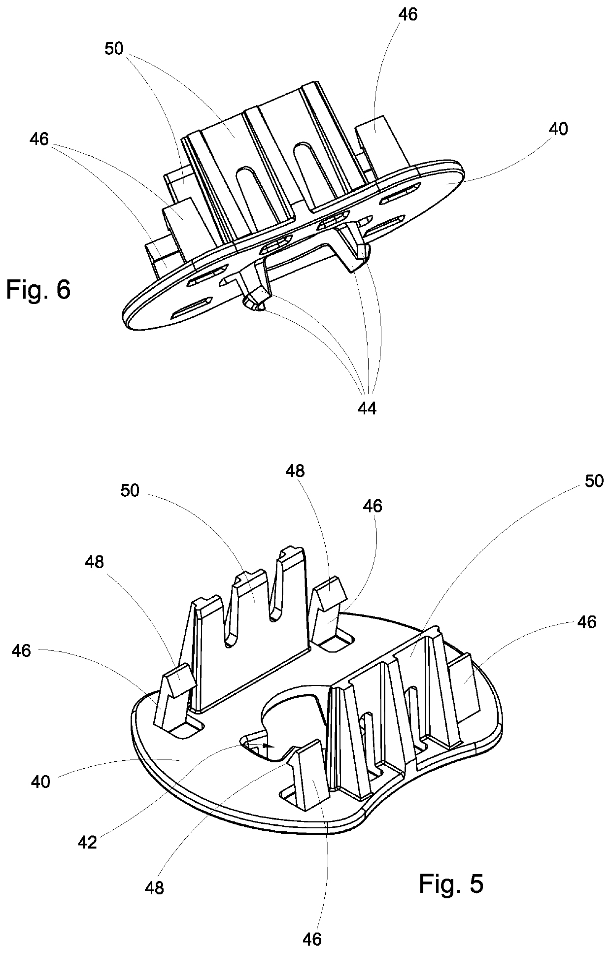
[0039]The support system 100 includes:[0040]a support foot 12 adapted to be placed on a reference ground and already subject of protection held by the holder of the present right;[0041]a connection disk 14 which is adapted to be fixed to the support foot 12 and in which openings 15 are formed;[0042]a receiving element 16 to be bound to the connection disk 14;[0043]a section bar 10 adapted to be received in the receiving element 16 in a stable manner;[0044]a connector 18 to be fixed to the section bar 10 by means of a screw 20 and adapted to be coupled with one or more planks A.

[0045]As it appears from FIGS. 2 and 4, the section bar 10 has an elongated shape and consists of a sheet metal 22 which is shaped in such a way that the cross section of the sa...


PUM


Abstract

Disclosed is a section bar and a support system for raised floors including the section bar. In particular, the section bar is particularly shaped and the presence of this section bar makes the support system fast and simple to assemble.

Description

[0001]This application is the U.S. national phase of International Application No. PCT / IB2019 / 058080 filed 24 Sep. 2019, which designated the U.S. and claims priority to IT Patent Application No. 102018000008855 filed 24 Sep. 2018, the entire contents of each of which are hereby incorporated by reference.[0002]The present invention refers in general to a support system for floors including a section bar. In particular, the present invention refers to a system that is fast and simple to assemble and designed to support floors and including a particularly shaped section bar.[0003]The raised floors are systems of raised flooring in which the walkable area rests on a structure that is elevated from the ground and is usually built using suspended modular elements. In this way, it is possible to obtain an inspectable technical compartment between the ground and the walkable plane. For example, this compartment can be useful for the passage of cables.[0004]As it is known, there exist vario...

Claims


Application Information

Patent Timeline
Patent Type & Authority Patents(United States)
IPC IPC(8): E04F15/024
CPCE04F15/02452E04F15/02458
Inventor CIPRIANI, ZENO
Owner DAKOTA GRP S A S DI ZENO CIPRIANI & C
Why Eureka
Try Eureka